Reaction injection molded members and method of forming

Inactive Publication Date: 2005-03-24
THE BOEING CO
View PDF23 Cites 15 Cited by
  • Summary
  • Abstract
  • Description
  • Claims
  • Application Information

AI Technical Summary

Benefits of technology

[0009] According to one aspect of the present invention, at least one elongate support member is disposed in the cavity so that the foam forms at least partially around the support member and the support member increases the strength and/or stiffness of the RIM member. The support member, which can be formed of reinforced thermoplastic laminate, Tedlar®, or fiberglass, can be disposed against the contour surface of the mold so that the support member defines a surface of the RIM member. One or more fasteners can be disposed in the cavity so that the member is formed with the fastener(s) at least partially disposed therein.
[00

Problems solved by technology

The characteristics of conventional reaction injection molded (RIM) parts do not meet the requisite standards for some applications.
Fu

Method used


Image

  • Reaction injection molded members and method of forming
  • Reaction injection molded members and method of forming
  • Reaction injection molded members and method of forming

Examples


Example

[0017] The present invention now will be described more fully hereinafter with reference to the accompanying drawings, in which some, but not all embodiments of the invention are shown. Indeed, this invention may be embodied in many different forms and should not be construed as limited to the embodiments set forth herein; rather, these embodiments are provided so that this disclosure will satisfy applicable legal requirements. Like numbers refer to like elements throughout.

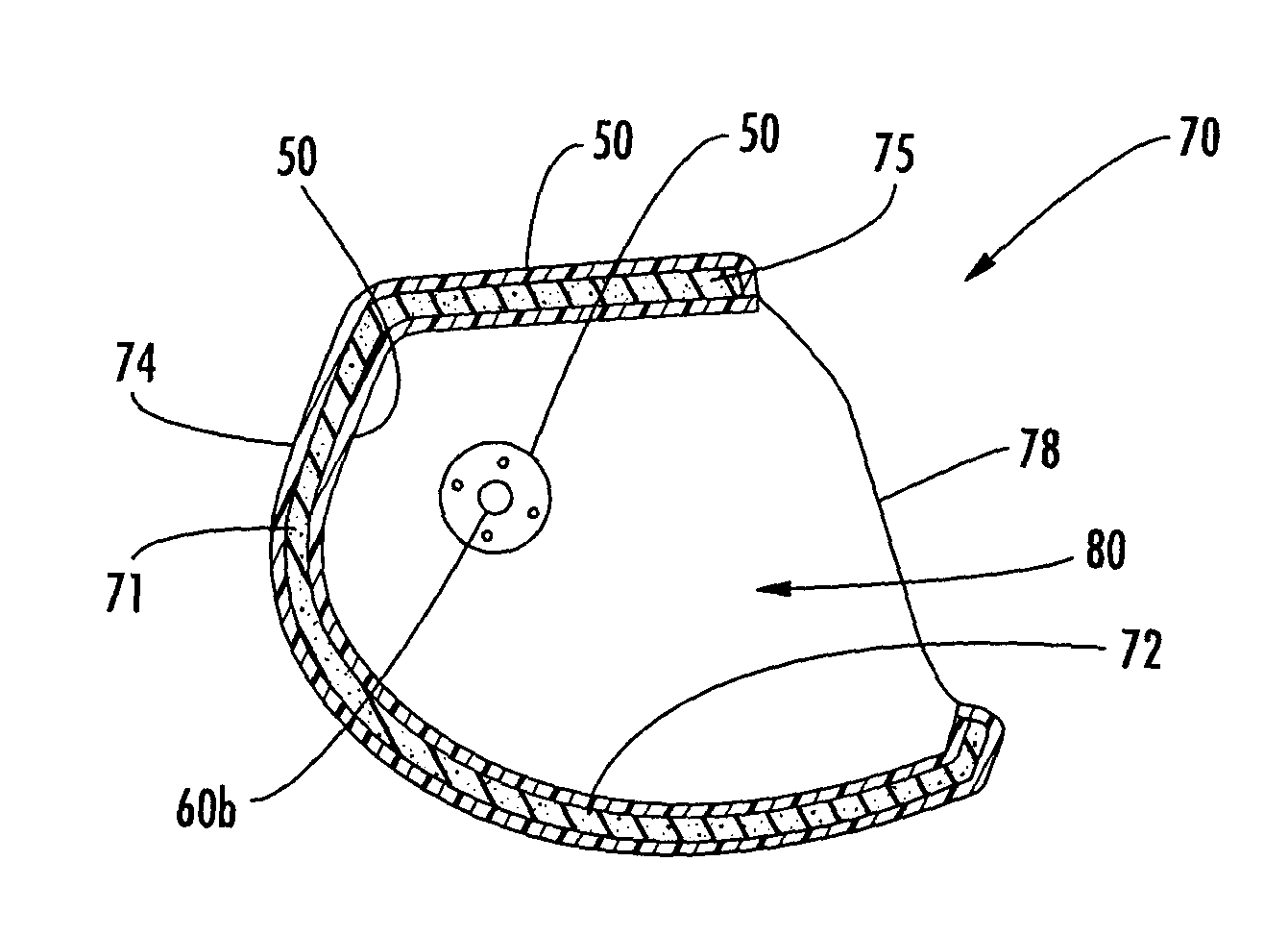
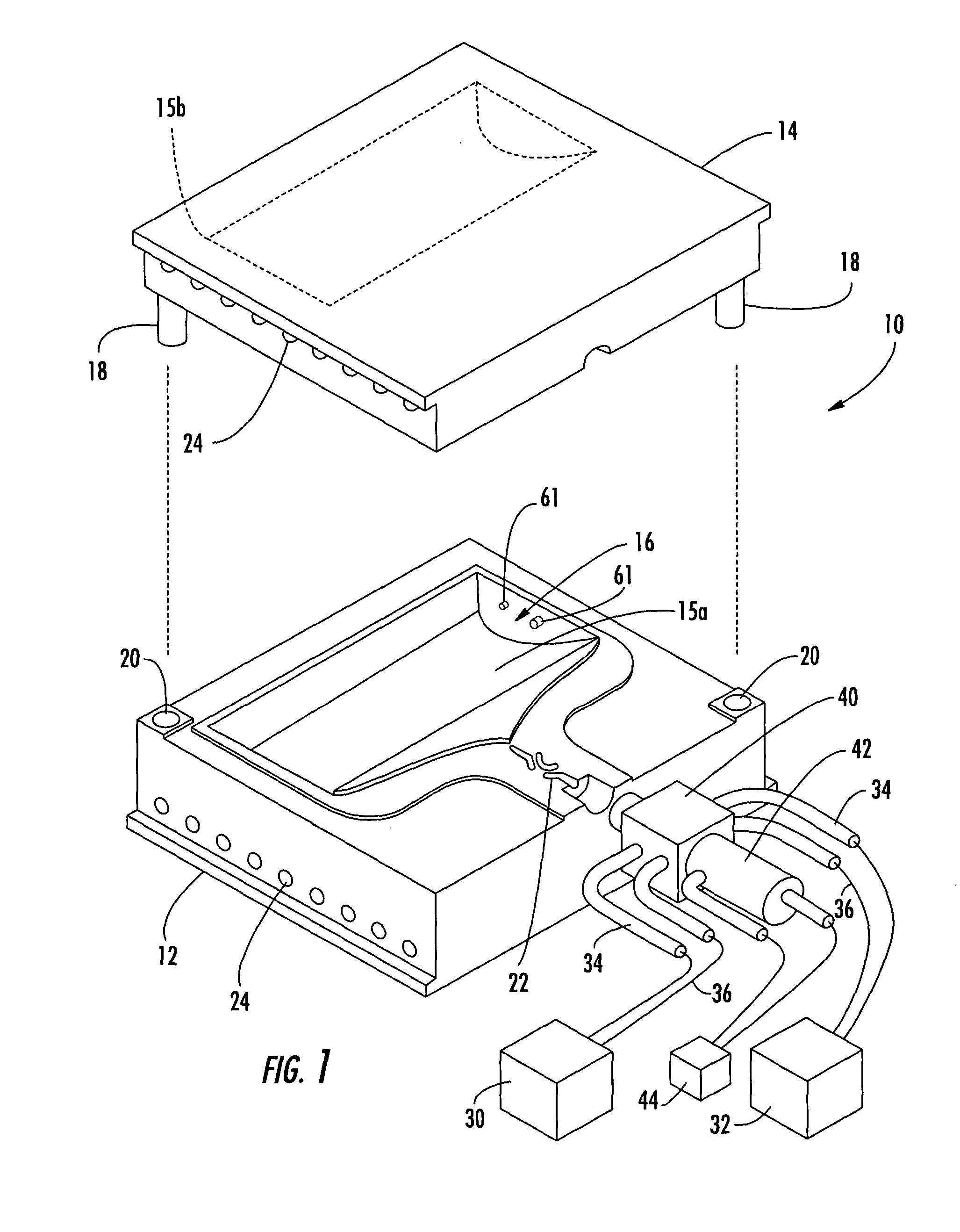
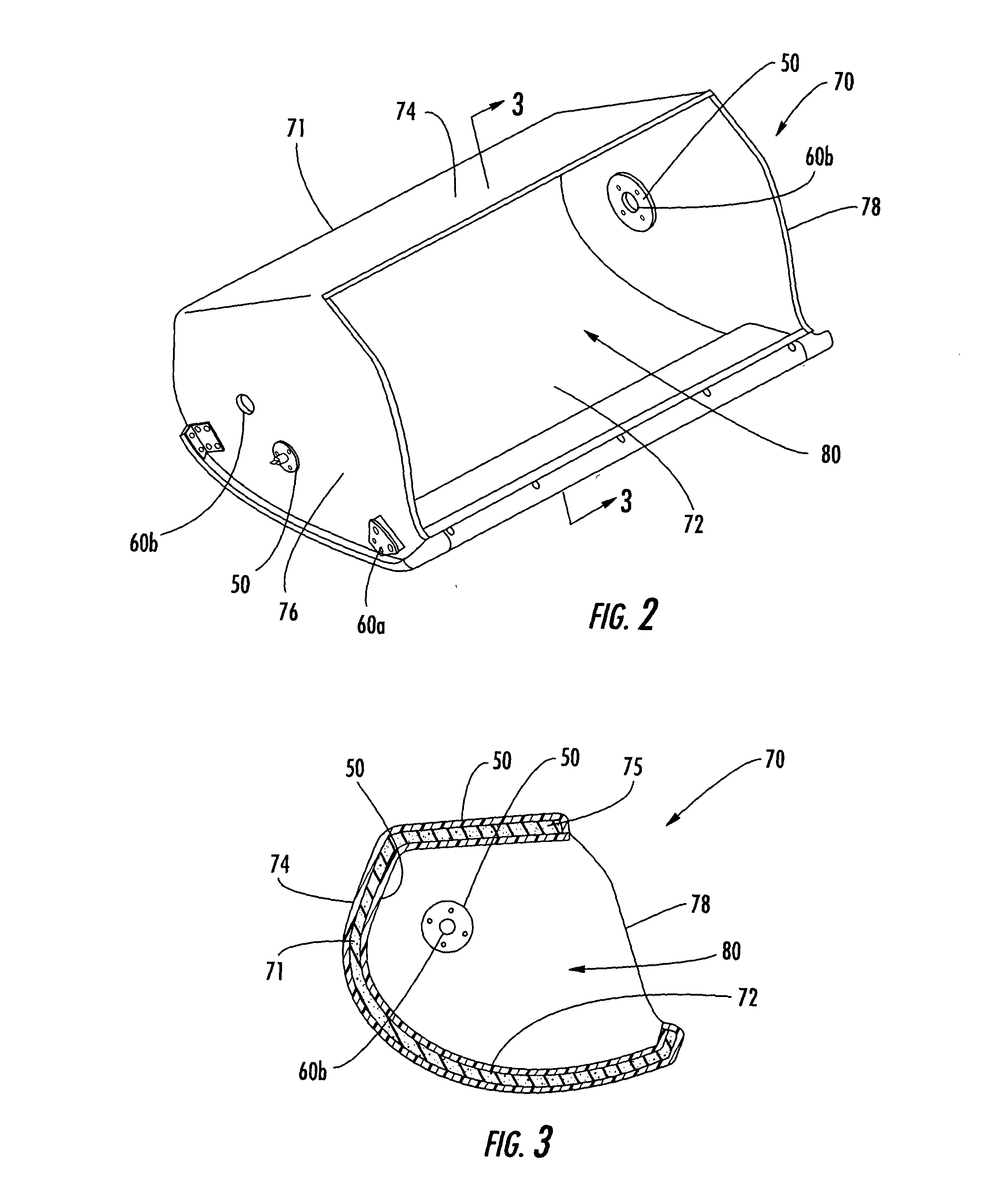
[0018] Referring now to the figures and, in particular, FIG. 1, there is shown an apparatus 10 for forming a reaction injection molded (RIM) member 70 (FIG. 2) according to one embodiment of the present invention. The apparatus 10 includes first and second co-operable mold members 12, 14 or dies that can be closed to form a mold defining a mold cavity 16. The mold cavity 16 has a predetermined contour that corresponds to the desired contour of the member 70. For example, the mold members 12, 14 shown in FIG. 1 c...


PUM

PropertyMeasurementUnit
Fractionaaaaaaaaaa
Fractionaaaaaaaaaa
Percent by massaaaaaaaaaa

Abstract

Reaction injection molded (RIM) members and a method for forming such members are provided. The members can be formed in a mold cavity defining a contour that corresponds to the desired contour of the members. A foam material, such as a combination of polyol and isocyanate is injected into the cavity with a blowing agent so that the foam material expands to form the low density member. The average density of the member can be less than about 6 pounds per cubic foot.

Description

BACKGROUND OF THE INVENTION [0001] 1) Field of the Invention [0002] The present invention relates to reaction injection molding of members and, in particular, members formed by reaction injection molding with improved properties, such as reduced density and improved fireworthiness. [0003] 2) Description of Related Art [0004] Reaction injection molding is conventionally used in the manufacture of members for medical devices, sporting equipment, and automobile trim parts. In one typical manufacturing method, first and second dies of a molding tool are used to form the part. With the dies in an open configuration, a liquid foaming material is dispensed onto a surface of one or both of the dies. The dies are then closed to encapsulate the foaming material in a cavity defined between the dies. The foaming material expands to fill the cavity, dries and hardens to form the foam part with a shape that corresponds to the shape of the die cavity. In addition, a laminar layer of material can b...

Claims


Application Information

Patent Timeline
IPC IPC(8): B29C33/00B29C44/12B29C67/24B64C1/12B64D11/00
CPCB29C33/0072B29C44/1271B29C67/246B29L2031/30Y10T428/24008B64C1/067B64D11/003Y10T428/233Y10T428/24273B29L2031/3005Y10T428/249986
Inventor GIDEON, DAVID E.JACKSON, EUGENE A.VAUGHAN, DAVID A.
Owner THE BOEING CO
Why Eureka
Try Eureka