
Chemiluminescently illuminated suction appliances

a technology of illumination and suction appliances, which is applied in the direction of luminescence, catheters, incision instruments, etc., can solve the problems of radiology, preventing the use of ambient lighting, and affecting the operation of procedures,

Inactive Publication Date: 2005-03-24
SIMON JAMES S +1
View PDF1 Cites 88 Cited by
  • Summary
  • Abstract
  • Description
  • Claims
  • Application Information

AI Technical Summary

Benefits of technology

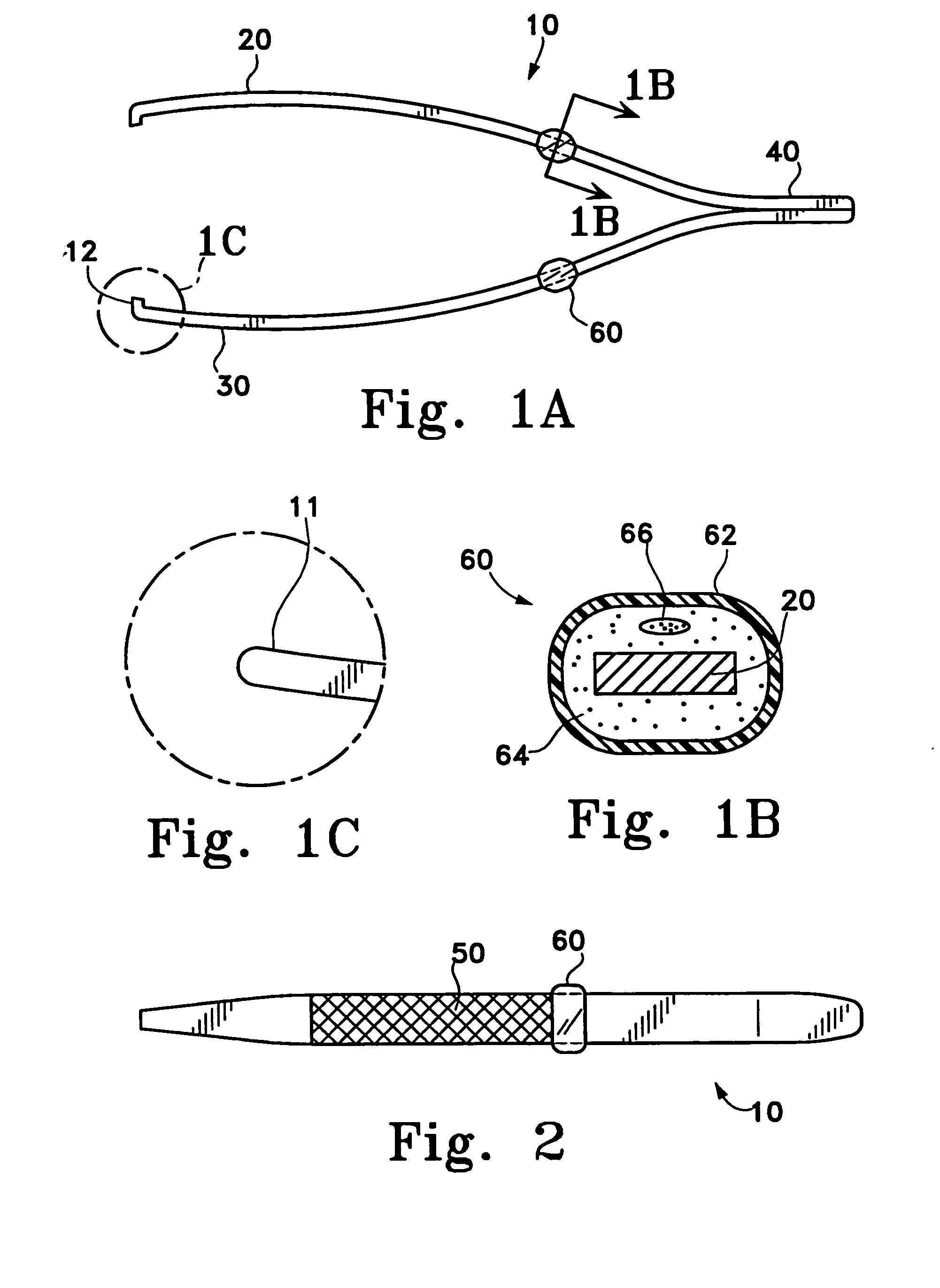
[0016] The chemiluminescent material may be of the types that are induced or catalyzed (similar to that sold in Cyalume “light sticks”). Chemiluminescent materials are well known and appropriate ones are readily available from commercial sources. The various materials of construction should be compatible for use within the human body. The devices may be designed and adapted in such ways that they are either disposable or re-useable or portions of the devices are disposable or re-useable.
[0017] The chemiluminescent regions of this invention may be integrated into the device itself, e.g., by placement of an open volume suitable for containing the chemil...

Problems solved by technology

Although ambient lighting may provide adequate illumination for the surgeon in certain situations, ambient lighting is not always available as an illumination option such as in the military and paramedic (emergency) environments.
Additionally, certain diagnostic procedures (e.g., radiology) preclude the use of ambient lighting because these procedures (e.g., fluoroscopy) are performed in a dark room or in lowered ambient lighting.
Such procedures are hindered by direct lighting.
However, a shortcoming of this technique is that additional attendants may not always be available and, even if the attendants are available, their presence increases the cost of the procedure.
Although use of fiber optics in medical appliances has reduced some of the above mentioned problems, fiber optically illuminated medical devices still require an external power or light source.
Fiber optically illuminated medical devices are thus not conveniently functional in many situations such as emergency or military scenarios.
Proper placement of medical devices during a procedure can be critical.
Lighting during intubation procedures is often inadequate and airway obstructions may compromise visualization of the proper anatomical pathways.
Not having adequate illumination not only could lead to failure of the procedure but could also result in irreversible injury to the patient.

Method used


Image

  • Chemiluminescently illuminated suction appliances
  • Chemiluminescently illuminated suction appliances
  • Chemiluminescently illuminated suction appliances

Examples


Embodiment Construction

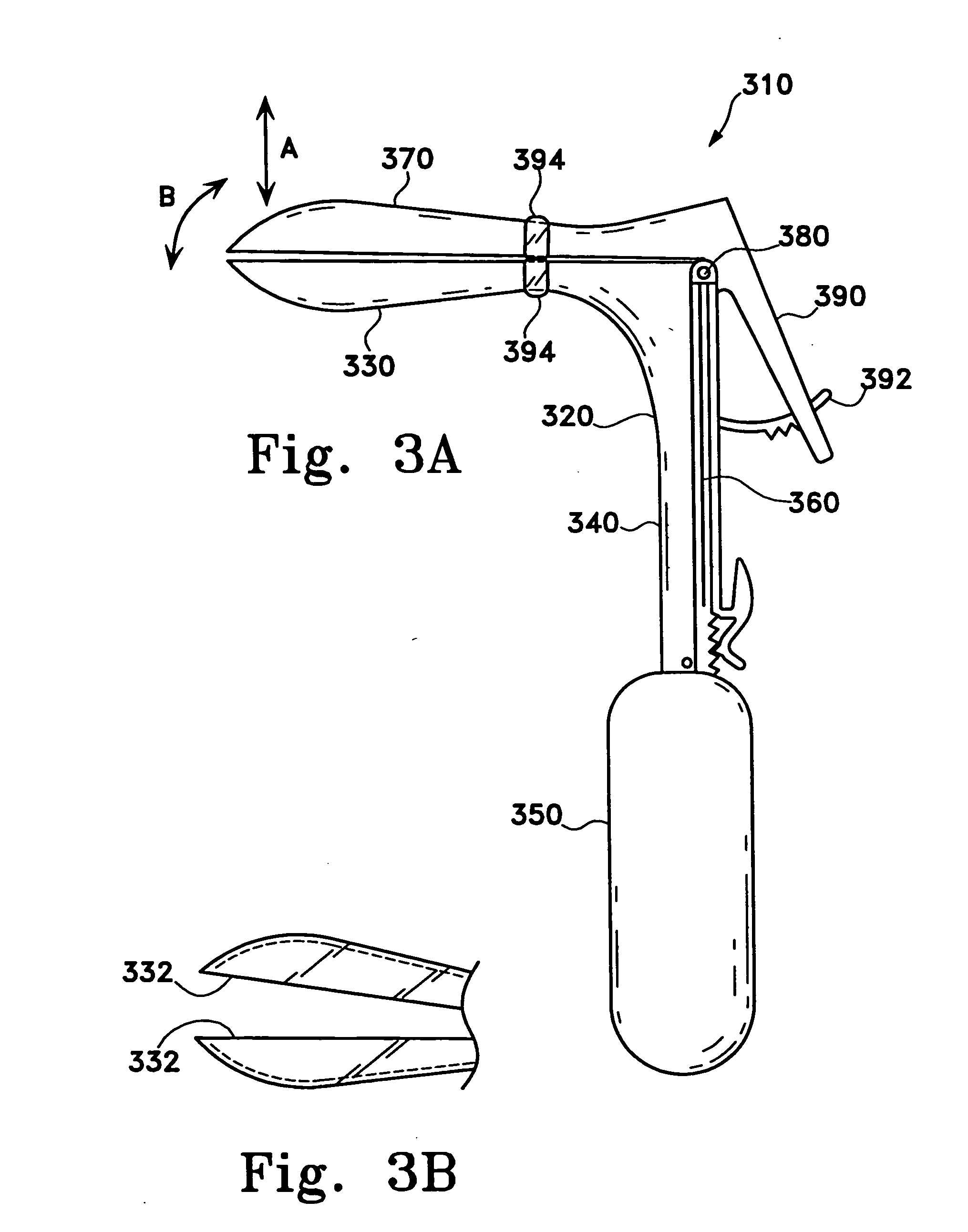
[0023] Medical appliances are described herein. The medical appliances may be directed and configured for various uses and procedures and have particular suitability where self illumination is advantageous such as in emergency and military environments. The described devices typically comprise a chemiluminescent source that provides illumination. The chemiluminescent source or region, as will be explained in more detail below, is variously coupled to, associated with, or incorporated into the device.

[0024] The chemiluminescent materials may be comprised of various chemicals that are well known to one skilled in the art to be able to provide luminescence when reacted with one another. A chemical luminescent reaction requires two or more chemicals to react with one another. When the reaction occurs, the electrons in the new product get excited, and they emit light when the electrons fall back into their normal orbits. Examples of chemiluminescent materials are disclosed in the follow...


PUM


Abstract

This invention relates to chemiluminescent suction devices and methods for using the devices. The devices may be useful as medical, industrial, and consumer products. They may be disposable and may employ an integrated or attachable chemiluminescent source. In some variations, the device may include a supporting structure or body that is at least partially translucent or transparent for transmitting chemiluminescent illumination.

Description

CROSS REFERENCE TO RELATED APPLICATIONS [0001] This application is a continuation application of PCT / US03 / 06868, filed Mar. 6, 2003, which claims benefit of U.S. Provisional Patent Application No. 60 / 416,079, filed Oct. 4, 2002 and U.S. Provisional Patent Application No. 60 / 362,492, filed Mar. 6, 2002, which are hereby incorporated by reference in their entirety.FIELD OF INVENTION [0002] This invention relates to devices that may be chemiluminescently illuminated and useful as medical, industrial, and consumer products. They may be disposable and may employ an integrated or attachable chemiluminescent source. In some variations, the device may include a supporting structure or body that is at least partially translucent or transparent for transmitting chemiluminescent illumination. BACKGROUND [0003] Safe and efficient use of many medical and dental appliances requires illumination. The illumination is desirably, amongst other things, precise, convenient, and not overly cumbersome or...

Claims


Application Information

Patent Timeline
IPC IPC(8): A61B1/00A61B1/06A61B1/247A61B1/267A61B1/32A61B17/00A61B17/02A61B17/30A61B17/32A61B17/34A61B19/00A61C1/08A61MA61M1/00A61M1/02A61M16/04A61M25/00A61M25/06A61M31/00F21K2/00
CPCA61B1/247A61B1/0661A61B1/32A61B17/00008A61B17/02A61B17/0206A61B17/30A61B17/3211A61B17/34A61B19/52A61B19/5202A61B2019/5204A61B2217/005A61C1/088A61C17/043A61M1/008A61M16/0488A61M25/0069A61M25/0082A61M25/0662A61B1/267A61B90/36A61B90/30A61B2090/304A61M16/0409A61C17/08A61M1/84
Inventor SIMON, JAMES S.SIMON, ROBERT A.
Owner SIMON JAMES S
Learn More