Annuloplasty apparatus and methods

a technology of annuloplasty and a tube is applied in the field of annuloplasty apparatus and methods, which can solve problems such as obstructing flow intake, and achieve the effect of facilitating tissue plication

Inactive Publication Date: 2005-03-24
COALESCENT SURGICAL
View PDF99 Cites 279 Cited by
  • Summary
  • Abstract
  • Description
  • Claims
  • Application Information

AI Technical Summary

Benefits of technology

[0018] The present invention involves annuloplasty systems that avoid problems and disadvantages of the prior art. The present invention involves an annuloplasty system for repairing a valve in a patient's heart. The system comprises a surgical implant, which includes a member having first and second end portions. The implant member further is configured and / or adapted to form a partial ring along a portion of one of the valve annulae of a patient's heart such as the mitral or tricuspid valve annulus. The implant member is axially elastic such that it can axially expand and contract and includes first and second anchors extending from the end portions of the implant member to anchor the implant in tissue such as the mitral or tricuspid valve annulus. The system can facilitate tissue plication (e.g., of the posterior annulus of the mitral valve or the anterior annulus of the tricuspid valve) and reinforcement of a valve annulus.
[0019] The partial ring configuration may reduce or minimize the risk of stenosis as compared to more bulky systems using full rings. This configuration also can reduce the amount of prosthetic material that is exposed to blood flow, thus, minimizing or eliminating the requirement for post-operative anticoagulation. Further, since the ends are not joined, the surgeon need not place anything on the anterior portion of the annulus (in the case of mitral valve repair), which otherwise could obstruct flow intake.
[0020] According to another aspect of the annuloplasty system, clips can be used in lieu of sutures to anchor or fasten the implant in the desired position. This eliminates cumbersome suturing approaches, simplifies implantation as compared to conventional methods, and facilitates minimally invasive (e.g., endoscopic) approaches to valve annuloplasty (e.g., mitral or tricuspid valve annuloplasty).

Problems solved by technology

Further, since the ends are not joined, the surgeon need not place anything on the anterior portion of the annulus (in the case of mitral valve repair), which otherwise could obstruct flow intake.

Method used


Image

  • Annuloplasty apparatus and methods
  • Annuloplasty apparatus and methods
  • Annuloplasty apparatus and methods

Examples


Embodiment Construction

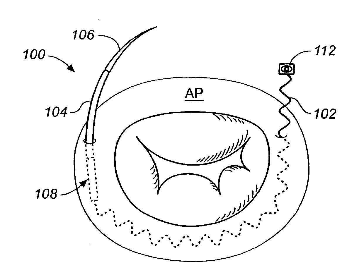
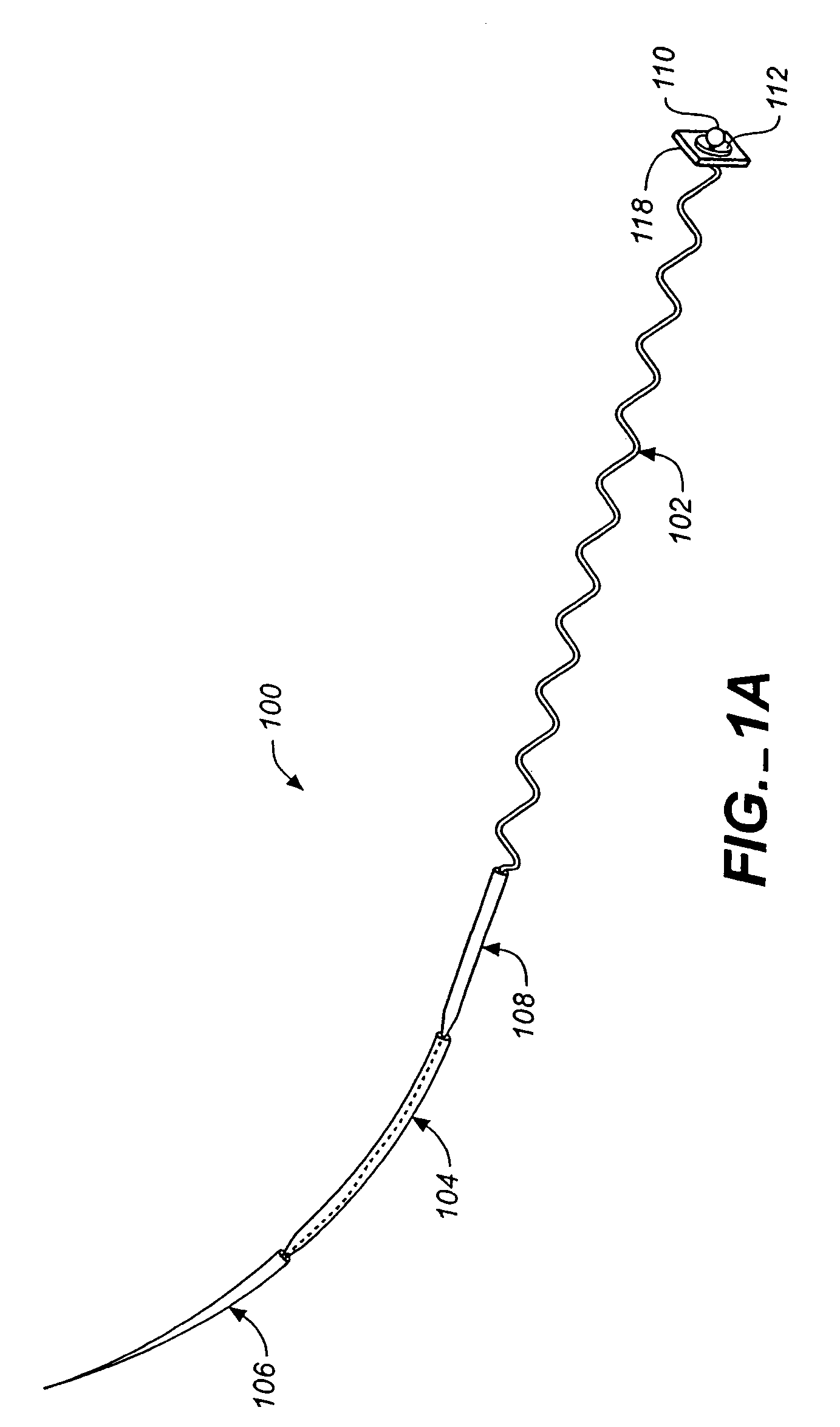
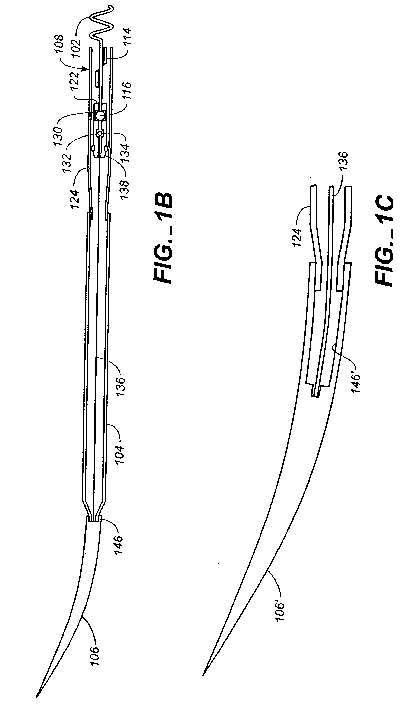
[0046] Referring to the drawings wherein like numerals indicate like elements, FIG. 1 illustrates an annuloplasty system 100 constructed in accordance with the principles of the invention. Annuloplasty system 100 generally comprises an implant member 102, a flexible member 104, and a needle 106. In the illustrated embodiment, system 100 also includes anchors or stoppers 112 (FIG. 1A) and 114 (FIG. 1B) and a release mechanism 108 to releasably couple the implant to the flexible member.

[0047] The distal end of the implant member may have an enlarged portion 110 as shown in the drawings. A stopper or anchor 112, preferably in the form of a disc and preferably welded to the distal end of the implant member, may be provided adjacent to the enlarged portion 110. Similarly, another stopper or anchor 114 may be provided adjacent to the implant's proximal enlarged portion 116 as shown in FIG. 1B. Stopper or anchors 112 and 114 also may referred to as retainers. Stopper 114 will be described...


PUM


Abstract

An annuloplasty system for repairing a valve in a patient's heart comprises a surgical implant including a member having first and second end portions. The implant member further is configured and / or adapted to form a partial ring along a portion of one of the valve annulae of a patient's heart such as the mitral or tricuspid valve annulus. The implant member is axially elastic such that it can axially expand and contract and includes first and second anchors extending from the end portions of the implant member. The anchors are adapted to anchor the implant in tissue such as the mitral or tricuspid valve annulus. The system can facilitate tissue plication (e.g., of the posterior annulus of the mitral valve or the annulus of the tricuspid valve) and reinforcement of a valve annulus.

Description

FIELD OF THE INVENTION [0001] The invention relates to heart valve repair and particularly to annuloplasty apparatus and methods. The invention is especially useful in mitral valve annuloplasty procedures, which generally involve mitral insufficiency (e.g., regurgitation when the mitral valve does not properly close). BACKGROUND OF THE INVENTION [0002] Essential to normal heart function are four heart valves, which allow blood to pass through the four chambers of the heart in one direction. The valves have either two or three cusps, flaps, or leaflets, which comprise fibrous tissue that attaches to the walls of the heart. The cusps open when the blood flow is flowing correctly and then close to form a tight seal to prevent backflow. [0003] The four chambers are known as the right and left atria (upper chambers) and right and left ventricles (lower chambers). The four valves that control blood flow are known as the tricuspid, mitral, pulmonary, and aortic valves. In a normally functi...

Claims


Application Information

Patent Timeline
Patent Type & Authority Applications(United States)
IPC IPC(8): A61F2/24
CPCA61F2/2451A61F2/2442
Inventor LEE, ANDREWFUNG, NORMANNGUYEN, JOHN D.DOAN, NGA T.SCHALLER, LAURENT
Owner COALESCENT SURGICAL
Why Eureka
Try Eureka