Pressure containing heat transfer tube and method of making thereof

a technology of heat exchanger and pressure-containing tube, which is applied in the direction of indirect heat exchanger, laminated elements, light and heating apparatus, etc., can solve the problems of increasing the cost of brazing process, reducing the efficiency of heat exchanger, and increasing the cost of raw materials and additional manufacturing steps

Inactive Publication Date: 2005-03-31
OUTOKUMPU OY
View PDF20 Cites 21 Cited by
  • Summary
  • Abstract
  • Description
  • Claims
  • Application Information

AI Technical Summary

Benefits of technology

[0009] The present invention meets the above-described needs and overcomes the drawbacks by providing a heat transfer tube and a method of forming a heat transfer tube with indented portions formed in the opposed walls. The indents may be cold welded or forge welded such that dimples or indentations meet in the middle of the tube. The bottom of a first indentation disposed on a first side of the tube is welded to the bottom of a second indentation formed in the opposite side of the tube.

Problems solved by technology

If the tubes have a thick bottom wall to prevent bulging, this causes the heat exchanger to be heavier than needed if it was made from a thin wall material.
The brazing material cannot be applied easily to certain materials and there are environmental issues with brazing.
Also, the brazing process adds cost due to the extra raw materials and additional manufacturing steps.

Method used


Image

  • Pressure containing heat transfer tube and method of making thereof
  • Pressure containing heat transfer tube and method of making thereof
  • Pressure containing heat transfer tube and method of making thereof

Examples


Embodiment Construction

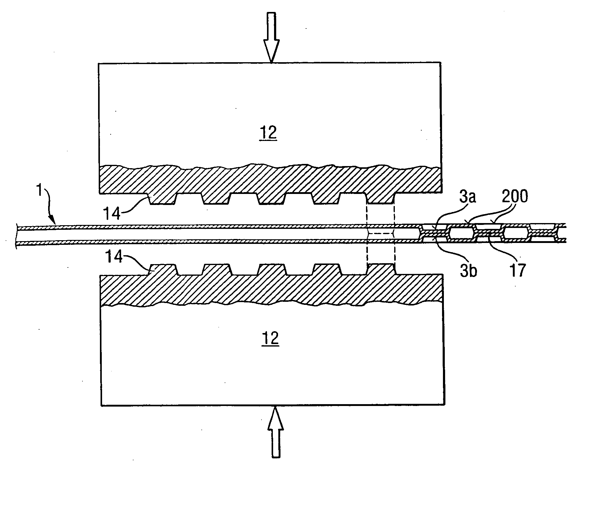
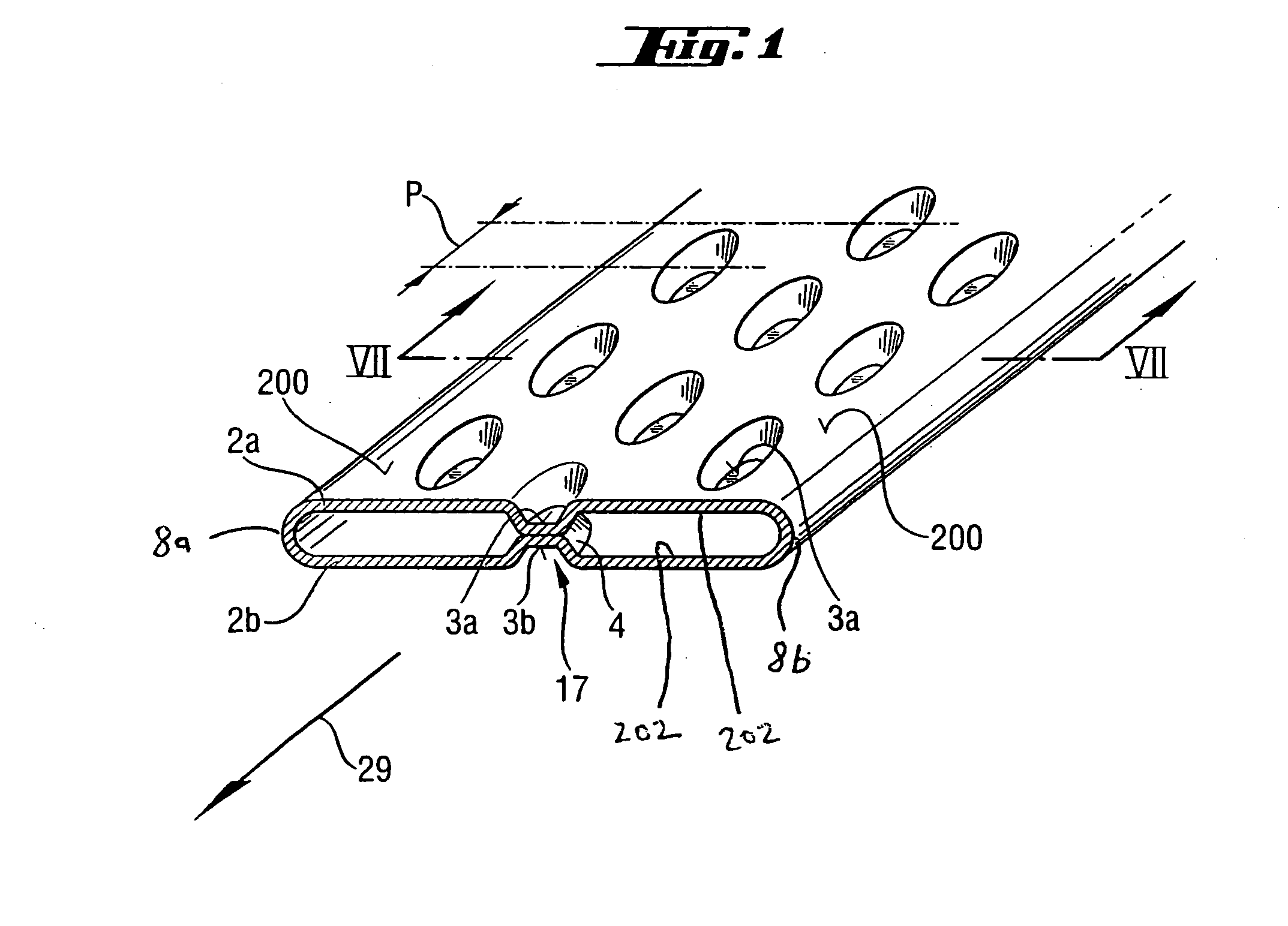
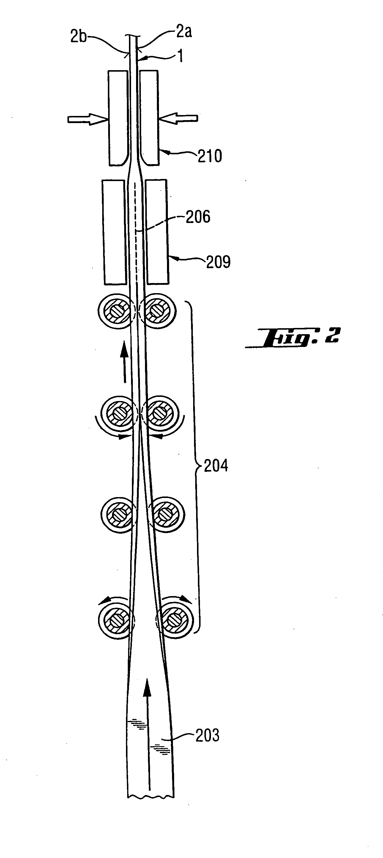
[0024] In FIG. 1, a tube 1 has major outer surfaces 200 formed on the outside of opposed walls 2a and 2b. Walls 2a and 2b are connected by curved end walls 8a and 8b. Walls 2a and 2b also have inner surfaces 202. The tube 1 may be constructed out of copper or other suitable materials. The tube 1 may be formed by several methods as will be evident to those of ordinary skill in the art. For example as shown in FIG. 2, tube 1 may be formed by taking flat stock 203 and roll forming it by turning up the edges gradually and then welding a seam 206 to join the edges. The seam is welded in a continuous process by an apparatus 209. Apparatus for continuous welding of tubes are generally known and therefore will not be described in detail herein. If the tube 1 is initially formed with a round profile, the tube may then be flattened by a press to form a flat tube having opposed walls 2a and 2b. Alternatively, the tube may be formed into a flat tube configuration and welded to shape. Also, othe...


PUM

PropertyMeasurementUnit
diameteraaaaaaaaaa
areaaaaaaaaaaa
widthaaaaaaaaaa

Abstract

A heat transfer tube and a method of forming a heat transfer tube with indents formed in the opposed walls. The indents may be cold welded or forge welded such that dimples or indentations meet in the middle of the tube. The bottom of a first indentation disposed on a first side of the tube is welded to the bottom of a second indentation formed in the opposite side of the tube.

Description

CROSS-REFERENCE TO RELATED APPLICATION [0001] The present application claims priority based on U.S. Provisional Patent Application No. 60 / 487,429 filed on Jul. 15, 2003, and entitled “Pressure Containing Heat Transfer Tube and Method of Making Thereof,” which is incorporated herein by reference.FIELD OF THE INVENTION [0002] The present invention relates to heat exchanger tubes and specifically to heat exchangers for use in high pressure applications, such as hydraulic coolers, radiators, HVAC systems, and CO2 systems. BACKGROUND OF THE INVENTION [0003] There is a need for heat exchangers that do not swell under high pressure, that increase the heat transfer of normal tubes by adding indents to the inner surface of the tube, and that enable the use of a higher conductance material for high pressure tube technology. [0004] There have been attempts to improve high pressure tubes by providing the tubes with thicker, heavier material for the bottom wall to reduce bulging. [0005] Also, so...

Claims


Application Information

Patent Timeline
Patent Type & Authority Applications(United States)
IPC IPC(8): B21C37/08B21D13/04F28D1/03F28F3/04
CPCB21C37/0803B21C37/158B21D13/04F28F2275/06F28F3/04F28F3/044F28D1/0391
Inventor ROTTMANN, EDWARD G.BENNETT, DONALD L.GOEBEL, TIMOTHY L.ANDERSSON, STIEGTANG, LIANGYOU
Owner OUTOKUMPU OY
Why Eureka
Try Eureka