
Pressure containing heat transfer tube and method of making thereof

A heat transfer tube, axis direction technology, applied in the direction of laminated components, heat exchange equipment, heat exchanger types, etc., can solve the problems of brazing material brazing environment, increase cost, etc.

Inactive Publication Date: 2006-08-30
OUTOKUMPU COPPER PROD
View PDF0 Cites 3 Cited by
  • Summary
  • Abstract
  • Description
  • Claims
  • Application Information

AI Technical Summary

Problems solved by technology

[0006] Brazing materials cannot be easily applied to a material and there are environmental concerns with using brazing
Also, the brazing process adds cost due to additional raw materials and additional processing steps
[0007] Micro-groove structure isolates channels to limit heat transfer improvement

Method used


Image

  • Pressure containing heat transfer tube and method of making thereof
  • Pressure containing heat transfer tube and method of making thereof
  • Pressure containing heat transfer tube and method of making thereof

Examples


Embodiment Construction

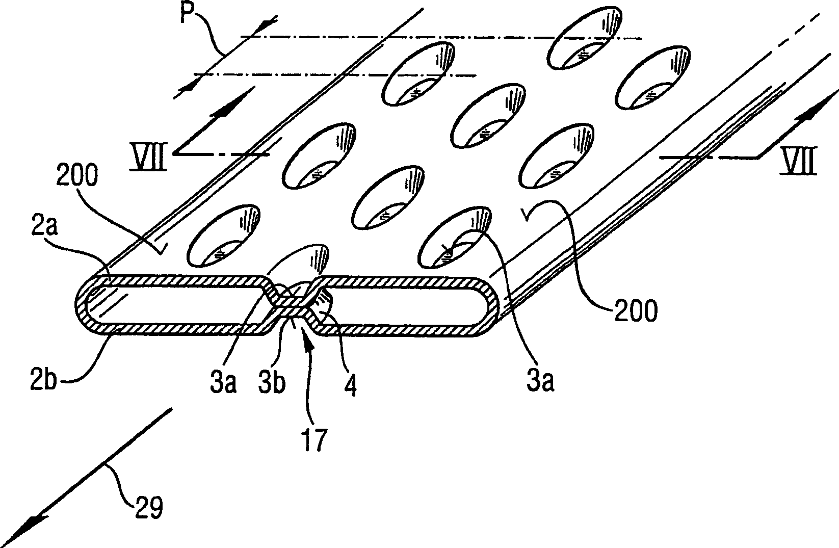
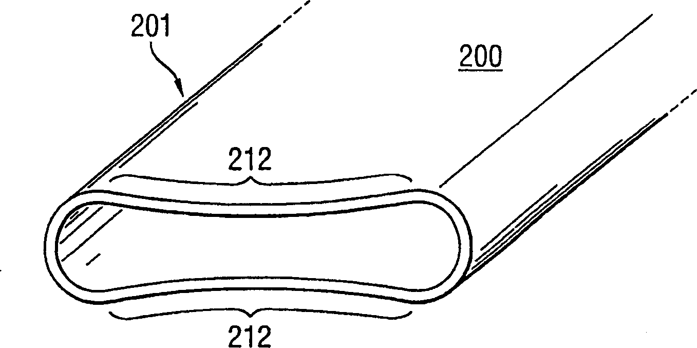
[0023] exist figure 1 In this case, the tube 1 has a main outer surface 200 formed on the outer side of the opposing walls 2a and 2b. Walls 2a and 2b are connected by a curved wall. The walls 2a and 2b also have inner surfaces. Tube 1 may consist of copper or other suitable material. The tube 1 can be formed by several methods apparent to those skilled in the art. For example figure 2 As shown in , the tube 1 can be formed by taking a flat stock 203, rolling its edges gradually with rollers 204 to form a tube, and then welding a seam 206 to join the edges. The seams may be welded by means 209 in a continuous process. Apparatus for continuous welding of pipes are generally known and will therefore not be described in detail here. If the tube 1 is first formed into a circular profile, the tube is then flattened by a press 210 to form a flat tube with opposing walls 2a and 2b. In other words, the tube can be formed into a flat tube structure and welded to form. Likewise,...


PUM

PropertyMeasurementUnit
diameteraaaaaaaaaa
areaaaaaaaaaaa

Abstract

A heat transfer tube and a method of forming a heat transfer tube with indents formed in the opposed walls. The indentations may be cold welded or forge welded such that dimples or indentations meet in the middle of the tube. The bottom of a first indentation disposed on a first side of the tube is welded to the bottom of a second indentation formed in the opposite side of the tube.

Description

technical field [0001] The present invention relates to a heat exchanger tube, and more particularly to heat exchangers used in high pressure applications such as hydraulic coolers, radiators, HVAC systems and CO 2 system. Background technique [0002] There is a requirement for heat exchangers not to expand under high pressure, and to increase the heat transfer of conventional tubes by adding indentations on the inner surface of the tubes, and to be able to utilize higher conductivity materials for high pressure tube technology. [0003] It would also be desirable to improve high pressure tubing by providing a tubing with a bottom made of thicker, heavier material to reduce bulging. [0004] Also, some tubes are made of aluminum and then brazed to create the dimples. Another type of tube includes stamped microgrooves for reinforcement. [0005] Each of the above approaches has drawbacks. If the tubes have a thicker bottom wall to prevent bulging, this results in a heavi...

Claims


Application Information

Patent Timeline
Patent Type & Authority Applications(China)
IPC IPC(8): F28D1/03F28F3/04B21D53/04B21C37/08B21D13/04
CPCB21C37/158F28F3/04B21C37/0803F28F3/044F28F2275/06F28D1/0391B21D13/04
Inventor E·G·罗特曼D·L·本内特T·L·格伯尔S·安德森唐良猷
Owner OUTOKUMPU COPPER PROD
Learn More