Fluid containment apparatus, and method of using same

a technology of containment apparatus and fluid, which is applied in the direction of liquid handling, packaging goods, separation processes, etc., can solve the problems of unsightly, inconvenience, and messy spillage, and achieve the effect of minimizing spillag

Active Publication Date: 2005-03-31
FRAM GROUP IP +1
View PDF7 Cites 28 Cited by
  • Summary
  • Abstract
  • Description
  • Claims
  • Application Information

AI Technical Summary

Benefits of technology

[0009] The present invention provides a fluid containment apparatus for minimizing spillage from a spin-on fluid filter during a filter change.
[0010] The apparatus hereof helps contain spillage from a spin-on fluid filter, such as a fuel filter or oil filter, during removal of the filter from an engine block or other substrate.
[0017] The present invention also relates to a method of minimizing fluid spillage during removal of a fluid filter from a substrate.

Problems solved by technology

However, when it becomes necessary to change a filter of this type, some fluid normally spills out of the filter when it is removed from its mounting area, particularly if the filter is mounted horizontally.
Such spillage is somewhat messy, unsightly and inconvenient.

Method used


Image

  • Fluid containment apparatus, and method of using same
  • Fluid containment apparatus, and method of using same
  • Fluid containment apparatus, and method of using same

Examples


first embodiment

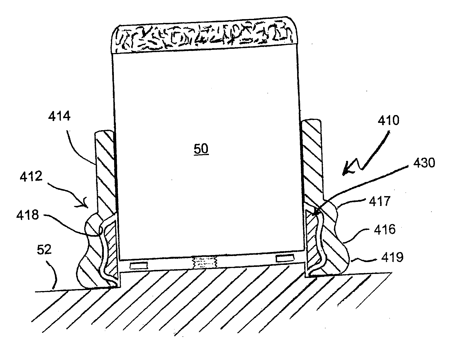
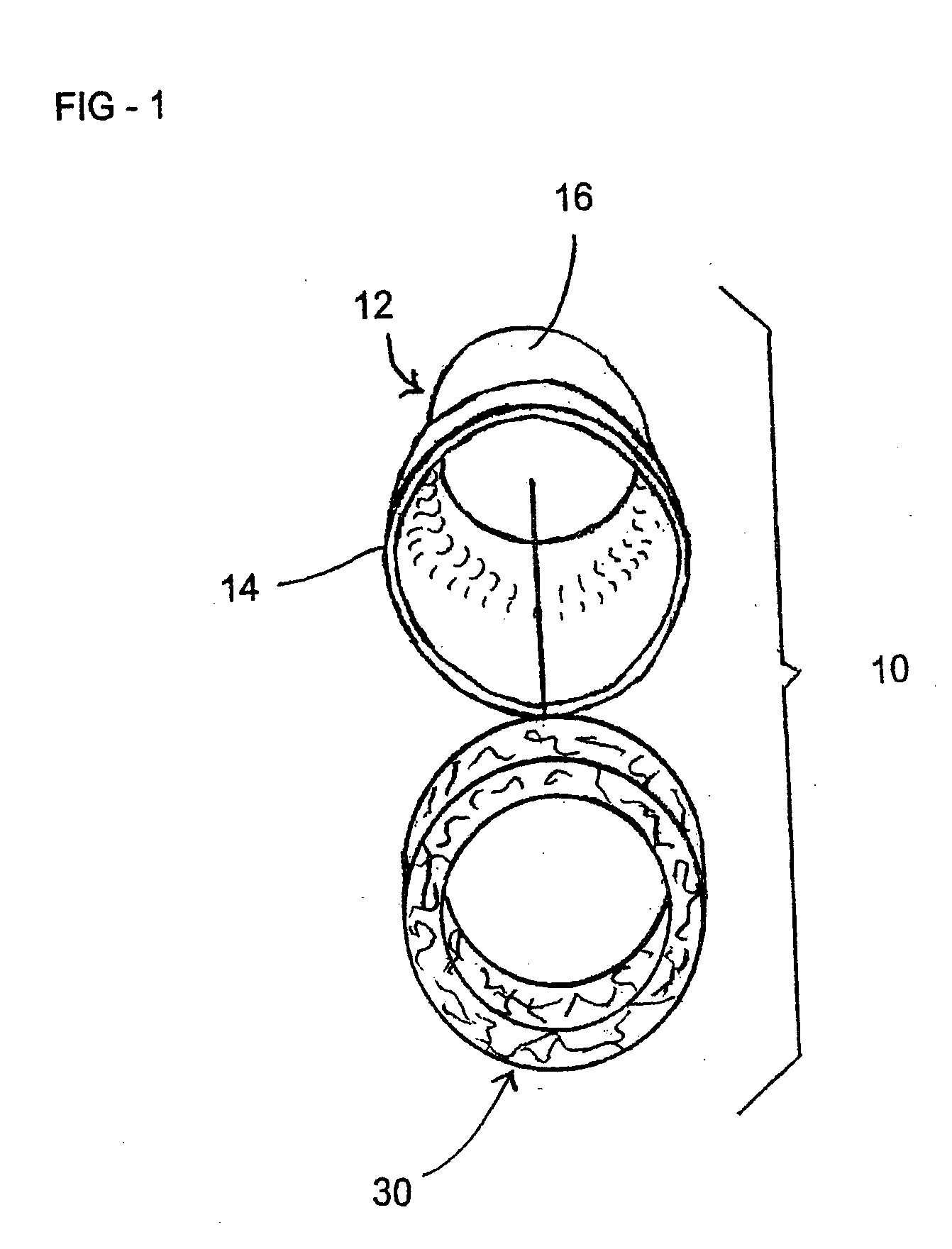
[0031] Referring now to FIGS. 1-3 of the drawings, a fluid containment apparatus, in accordance with the invention, is shown generally at 10. The apparatus 10 is provided for use in changing a spin-on fluid filter 50 (FIG. 3), to minimize spillage therefrom during removal of the filter from an engine block or other substrate 52.

[0032] An apparatus 10 according to the first embodiment includes a flexible boot 12, and an absorbent member 30 associated with the boot. The absorbent member 30 may be attached to the boot 12, or alternatively, may be separate from, and nestingly received inside the boot, to fit between the boot and a filter 50.

[0033] The Filter Boot

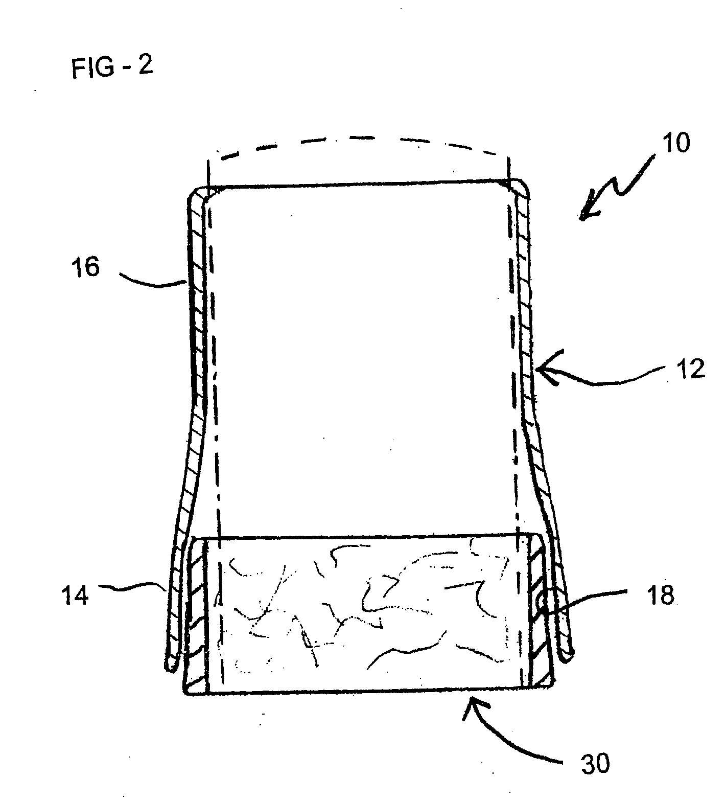
[0034] In the embodiment of FIGS. 1-3, the boot apparatus 10 includes a boot 12 with a substantially cylindrical boot body, including a flared bell portion 14, for placement surrounding and spaced away from a filter 50, and a constricted portion 16 for placement closely surrounding a portion of the filter.

[0035] The constrict...

second embodiment

[0043] Second Embodiment

[0044] A fluid containment apparatus 110 in accordance with a second embodiment of the invention is shown in cross-section in FIG. 4. The fluid containment apparatus 110 of FIG. 4 is similar to the apparatus 10 of FIGS. 1-3, as previously described, except that the boot 103 thereof is modified from the boot 12 of the first embodiment.

[0045] In the embodiment of FIG. 4, the boot 103 is preferably formed by dipping a hollow annular cylinder-shaped mandrel into a liquid plastic material, preferably a thermoplastic such as a vinyl polymer to form a layer of liquid plastic on the inner cylindrical surface of the mandrel, the outer cylindrical surface of the mandrel, and one end of the mandrel. The liquid plastic layer is then solidified, e.g. by cooling, and a solid plastic (preferably flexibly resilient) element in the shape of boot 103 is removed from the mandrel. In this dual thickness embodiment, the boot body includes a narrow inner section 104, and a wide o...

third embodiment

[0046] Third Embodiment

[0047] Referring now to FIGS. 5-6, a fluid containment apparatus according to a third embodiment of the invention is shown generally at 310 (FIG. 6). The apparatus 310 according to the third embodiment is substantially similar to the apparatus 10 of the first embodiment as described herein, including a boot 12, which is identical to the boot of the first embodiment. However, in this third embodiment 310, the absorbent member 330 is formed as a flat section of nonwoven material, which is folded into a cylindrical configuration, and placed inside of the bell section 16 of the boot 12.


PUM

PropertyMeasurementUnit
lengthaaaaaaaaaa
cylindrical shapeaaaaaaaaaa
thermoplasticaaaaaaaaaa

Abstract

A spillage-control boot apparatus for use during removal of a spin-on fluid filter from an engine block or other substrate. The boot apparatus includes a boot with a substantially cylindrical boot body, including a flared bell portion for placement surrounding a filter, and a constricted portion integrally attached to and extending from the flared bell portion, for placement closely surrounding a portion of the filter. The flared bell portion of the boot body is adapted to form an annular pocket therein when the boot is placed surrounding a cylindrical filter. The apparatus also includes an absorbent member, for placement in the flared bell portion of the boot body, for absorbing spillage from the filter base when the filter is removed from the substrate.

Description

BACKGROUND OF THE INVENTION [0001] 1. Field of the Invention [0002] The present invention relates to a fluid containment apparatus for use with a spin-on filter cartridge, and to a method of using the described apparatus. More particularly, the present invention relates to a composite boot apparatus, including a flexible boot and an absorbent member associated therewith, and to a method of using the described boot apparatus to minimize spillage during removal of a spin-on filter cartridge. [0003] 2. Description of the Background Art [0004] Cartridge-type fluid filters, of the spin-on variety, are well known and are widely used, for example as engine oil filters, and as fuel filters in gasoline filling stations. However, when it becomes necessary to change a filter of this type, some fluid normally spills out of the filter when it is removed from its mounting area, particularly if the filter is mounted horizontally. Such spillage is somewhat messy, unsightly and inconvenient. [0005] ...

Claims


Application Information

Patent Timeline
Patent Type & Authority Applications(United States)
IPC IPC(8): B01D27/00B01D35/31
CPCB01D35/31B01D27/00
Inventor ZULAUF, GARY B.LYNCH, MICHAEL S.
Owner FRAM GROUP IP
Why Eureka
Try Eureka