
Apparatus for holding a paint tray

a technology for paint trays and accessories, applied in the field of paint accessories, can solve the problems of inability to get out, time-consuming cleaning of spilled paint, and large increase the chance of spilling paint, and achieve the effect of being easily moved

Inactive Publication Date: 2007-09-13
ELLIS MARK R
View PDF7 Cites 7 Cited by
  • Summary
  • Abstract
  • Description
  • Claims
  • Application Information

AI Technical Summary

Benefits of technology

[0007]It is therefore one of the primary objects of the invention to provide an apparatus for holding a paint tray during painting which is relatively easy to use.
[0008]Another object of the present invention is to provide a paint tray which will substantially minimize the spillage of paint.
[0009]Still another object of the present invention is to provide a paint tray which is relatively inexpensive to manufacture.
[0010]Yet another object of the present invention is to provide a paint tray which can be stored in a relatively small space when not in use.
[0011]An additional object of the present invention is to provide a paint tray which is easily transported between job sites.

Problems solved by technology

When the user is finished with the tray and it is left on the ladder it is unstable and may spill paint therefrom. if the tray is left on the floor it has to be continuously moved, or get kicked around by the user.
The chances for accidentally spilling paint is, therefore, greatly increased.
Additionally, clean up of such spilt paint is time consuming and if the paint is spilled on carpet it may be impossible to get out.
Further, the paint is no longer useable thereby adding to the expense on painting.

Method used


Image

  • Apparatus for holding a paint tray
  • Apparatus for holding a paint tray
  • Apparatus for holding a paint tray

Examples


Embodiment Construction

, particularly, when such description is taken in conjunction with the attached drawing figures and appended claim.

BRIEF DESCRIPTION OF THE DRAWINGS

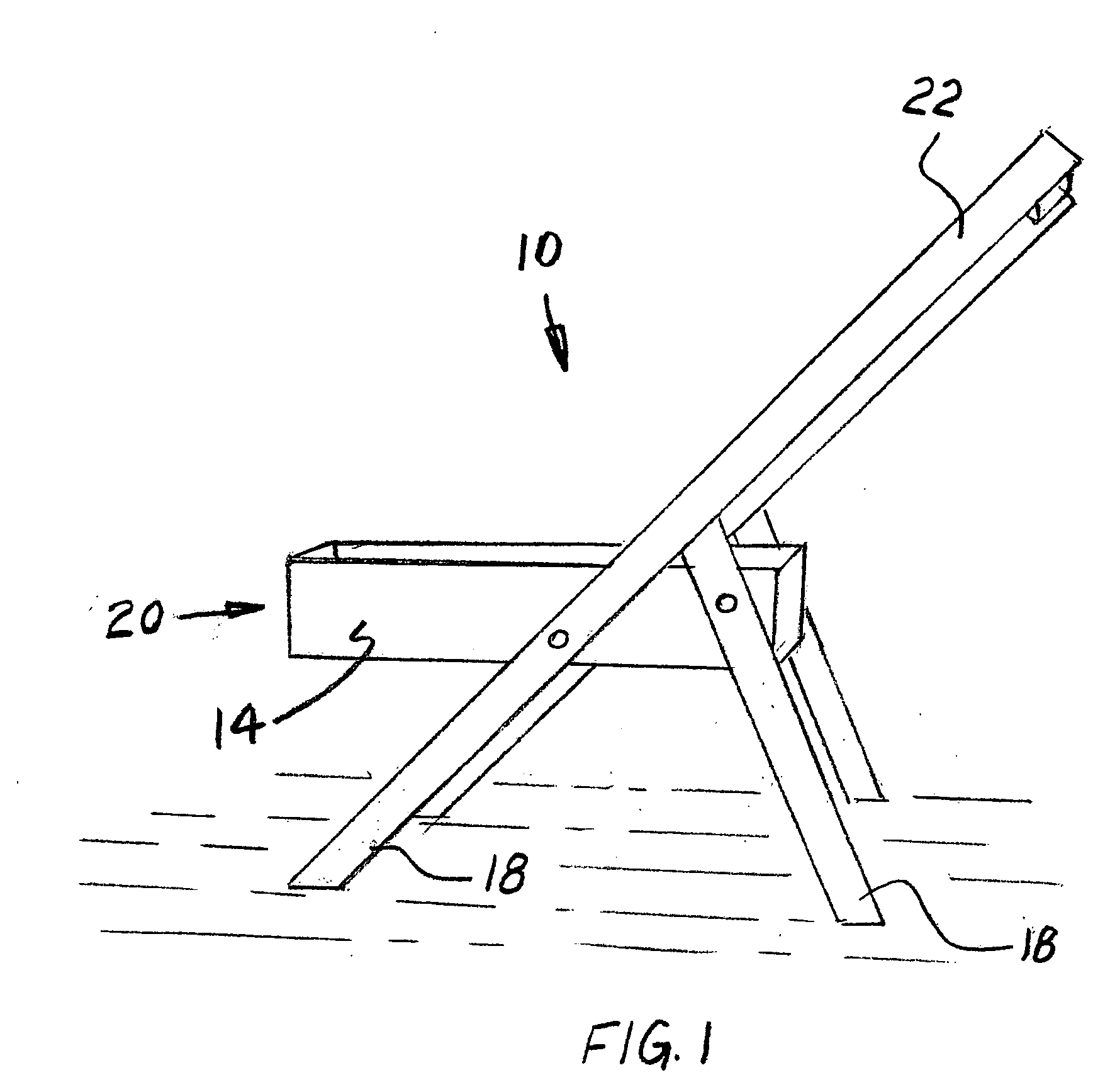
[0014]FIG. 1 is a perspective view of the apparatus for holding a paint tray according to a presently preferred embodiment of the invention;

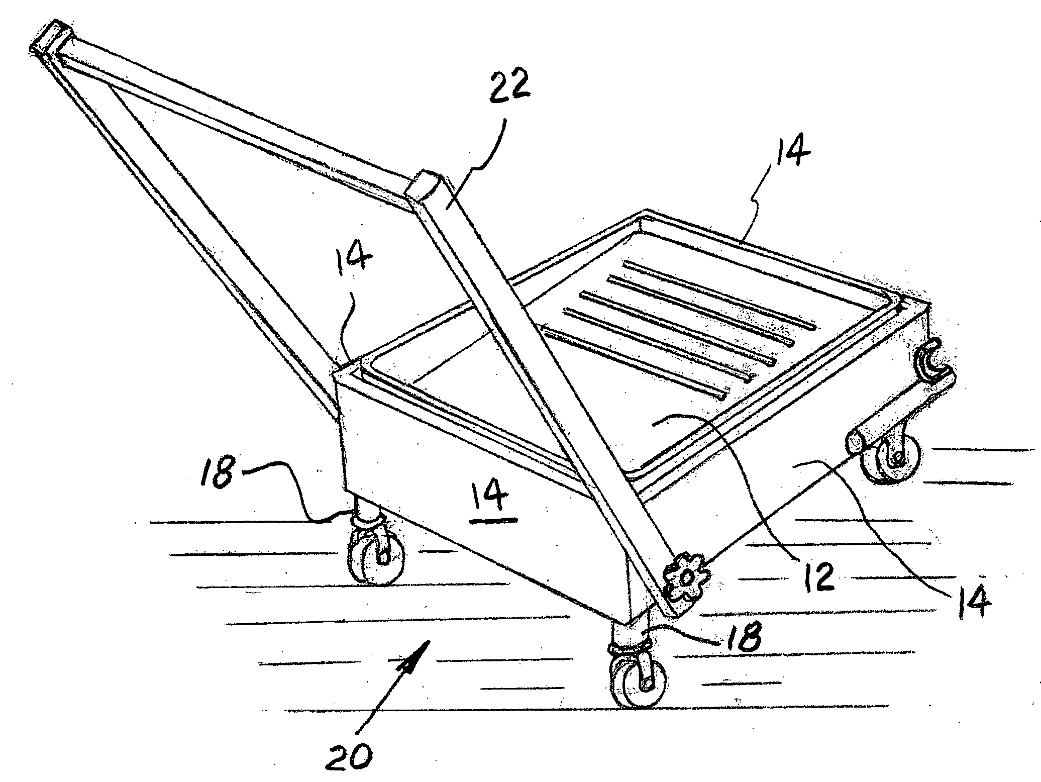
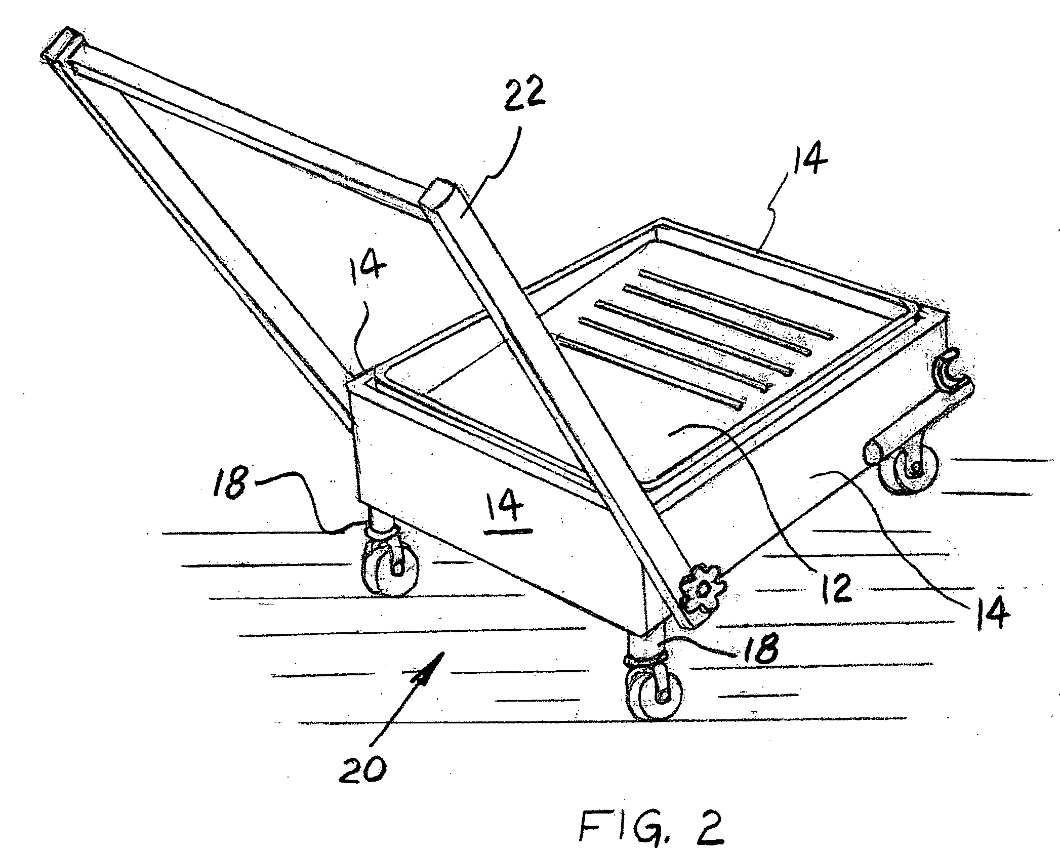
[0015]FIG. 2 is a perspective view of the apparatus for holding a paint tray according to an alternative embodiment of the present invention; and

[0016]FIG. 3 is a bottom view of the apparatus for holding a paint tray illustrated in FIG. 2.

BRIEF DESCRIPTION OF A PRESENTLY PREFERRED AND VARIOUS ALTERNATIVE EMBODIMENTS OF THE PRESENT INVENTION

[0017]Prior to proceeding to the more detailed description of the present invention it should be noted that, for the sake of clarity and understanding, identical components having identical functions have been identified with identical reference numerals throughout the several views illustrated in the attached drawing figures.

[0018]Now reference is made more partic...


PUM


Abstract

An apparatus for holding a paint tray which allows such tray to be readily moved without risk of spilling paint therefrom. Such apparatus includes a frame member having at least three vertically disposed side wall members. A predetermined length of two of these side wall members being longer that is a predetermined length of any remaining side wall members. Further, there is at least one horizontally disposed support member positioned at least one of intermediate each end of such side wall members and below a bottom surface of such side wall members. The final essential element of the frame member is a plurality of leg members disposed closely adjacent an outer perimeter of and attached to such frame member. Rollers are attached to a bottom of each of such leg members for facilitating movement of such apparatus over a surface and a handle is attached to such frame member for moving the apparatus as required while painting.

Description

CROSS-REFERENCE TO RELATED APPLICATION[0001]This application relates to and claims priority from U.S. Provisional Patent Application Ser. No. 60 / 657,304 filed Jan. 9, 2006.FIELD OF INVENTION[0002]The present invention relates, in general, to painting accessories and, more particularly, this invention relates to an apparatus for a holding a paint tray in a more advantageous position for painting.BACKGROUND OF THE INVENTION[0003]Prior to the present invention, a paint tray is either hooked unto a ladder when it is in use or set on a table or floor. When the user is finished with the tray and it is left on the ladder it is unstable and may spill paint therefrom. if the tray is left on the floor it has to be continuously moved, or get kicked around by the user.[0004]The chances for accidentally spilling paint is, therefore, greatly increased. Additionally, clean up of such spilt paint is time consuming and if the paint is spilled on carpet it may be impossible to get out.[0005]Further, ...

Claims


Application Information

Patent Timeline
IPC IPC(8): A47K1/04B62B1/00
CPCB62B3/10B44D3/14
Inventor ELLIS, MARK R.
Owner ELLIS MARK R
Learn More