Apparatus and method for storing slides in an angular arrangement

Active Publication Date: 2005-03-31
CYTYC CORP
View PDF3 Cites 2 Cited by
  • Summary
  • Abstract
  • Description
  • Claims
  • Application Information

AI Technical Summary

Benefits of technology

[0015] The fanning arrangement can be a vertical fanning arrangement, a horizontal fanning arrangement, or a combination thereof. Further, in the fanning arrangement, slides that are positioned further away from the base member (on the hig

Problems solved by technology

In conventional transport systems, the fingers are typically required to select an individual slide, but may instead, inadvertently select two slides due to tolerances in stacking mating machined components, such as a cartridge base and fingers extending from the platform.
More specifically, the platform fingers may not be able to engage only one slide at a time unless the engaging lip height is reduced, since the slides are aligned directly on top of each other.
As a result of this lower lip height, conventional systems may not reliably and consistently select a single slide, thereby resulting in selection and processing errors and processing system adjustments and inefficiencies.
Further, stacking multiple slides on top of each other can result in substantial weight being applied to lower slides in the stack, particularly to the bottom slide.
Excessive weight can also damage or break stacked slides.
Additionally, it may be more difficult to remove a slide out from beneath the stack due to the downward forces as a result of excessive weight and lateral friction forces between the slides.
Further, even assuming the slide is removed from the bottom of the stack, the weight and friction may result in the slide not being accurately placed on the fingers.
While some lateral friction forces may be alleviated through the use of, for example, a spray lubricant, spraying individual slides is time consuming and inconvenient.

Method used


Image

  • Apparatus and method for storing slides in an angular arrangement
  • Apparatus and method for storing slides in an angular arrangement
  • Apparatus and method for storing slides in an angular arrangement

Examples


Embodiment Construction

[0025] In the following description, reference is made to the accompanying drawings which form a part hereof, and which show by way of illustration specific embodiments in which the invention may be practiced. It is to be understood that other embodiments may be utilized as structural changes may be made without departing from the scope of the present invention.

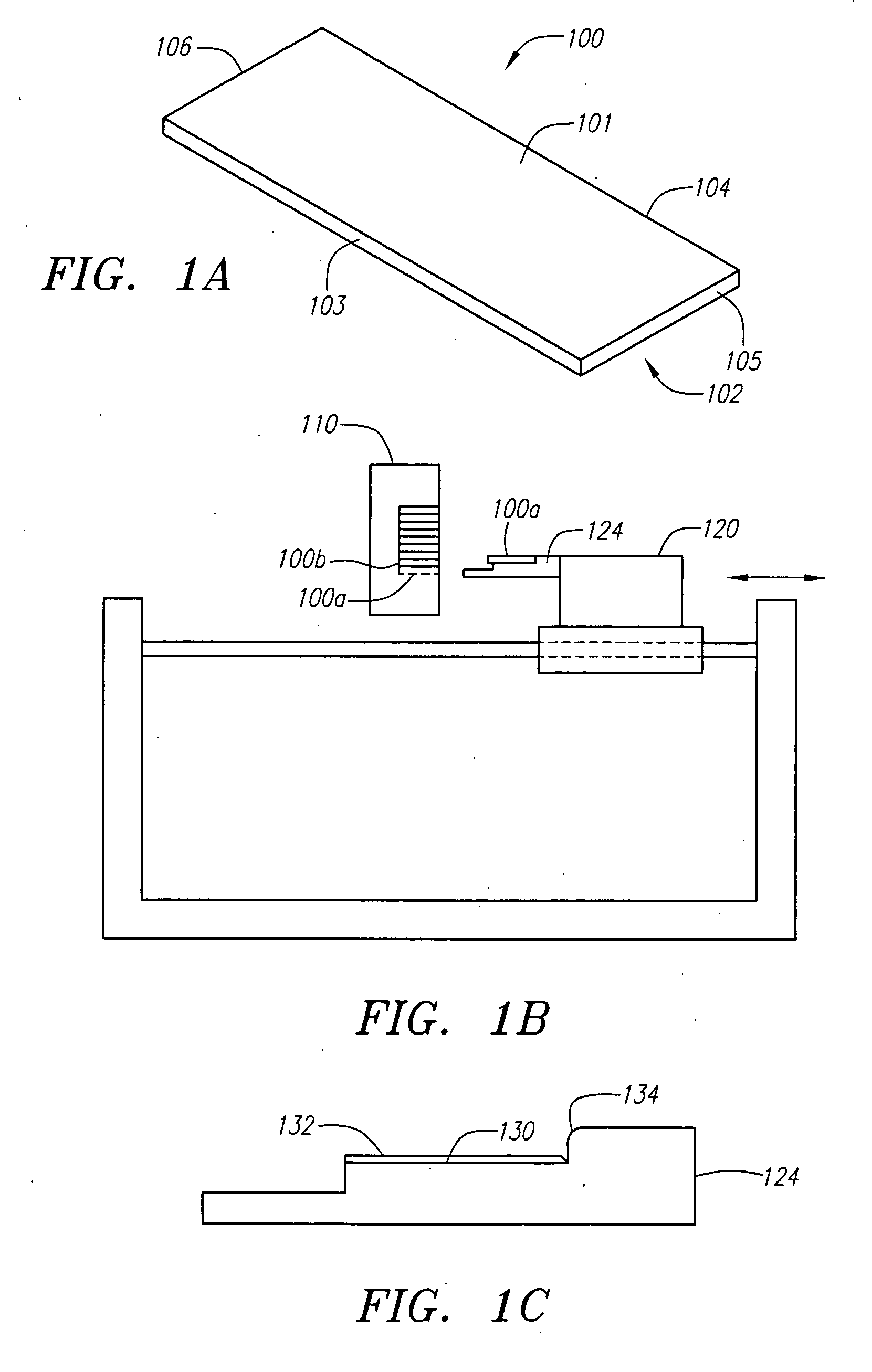
[0026] Referring to FIG. 1A, a typical conventional test or sample slide 100 has a top surface 101, a bottom surface 102, a first side 103, a second or opposite side 104, a first edge 105, and a second or opposite edge 106. Persons of ordinary skill in the art will recognize that the present invention can be used with various slide 100 shapes and sizes.

[0027] Referring to FIG. 1B, slides 100 are typically maintained in a storage apparatus or cartridge 110. A bottom slide 100a in a stack of slides 100 is typically removed or “picked” from the cartridge 110 by a slide selection or transport or translation system 120. A typica...


PUM


Abstract

An apparatus and method for storing slides in an angular, offset or fanning arrangement. The apparatus includes a base member and two support members. At least one of the base member, the first support member, and the second support member is arranged at an angle. With this configuration, the plurality of slides are angularly stacked on the base member and between the first and second support members. A bottom slide of the plurality of slides is dispensed through a slot defined between one of the lateral support members and the base member. The fanning arrangement can be a vertical fanning arrangement, a horizontal fanning arrangement, or a combination thereof.

Description

FIELD OF THE INVENTION [0001] The present invention relates slide storage mechanisms, and, more particularly, to an apparatus and method of storing slides in a non-overlapping arrangement, such as an angled, offset or fanning arrangement. DESCRIPTION OF RELATED ART [0002] Medical professionals and technicians utilize glass or plastic test slides to conduct various cytological testing and analyses. Slides are typically stored in and dispersed from a storage mechanism, such as a cartridge. [0003] In some applications, a slide selection or transport system picks or selects a slide from the cartridge and carries the slide to a processing or analysis station. One known transport system includes a platform with fingers extending from the platform. When a slide is to be retrieved from the cartridge, the fingers are advanced to engage a side of a bottom slide in a stack of slides. [0004] Conventional slide cartridges typically arrange slides in a stack in which one slide is placed directly ...

Claims


Application Information

Patent Timeline
IPC IPC(8): B01L9/00B65G11/20B65G59/00B65G59/06G01N1/31G01N35/00G01N35/04
CPCB01L9/52B01L2300/0822B65G11/203B65G59/067G01N35/026G01N2035/00039G01N2035/00138G01N2035/0425G01N1/312
Inventor FICHERA, STEPHEN L.
Owner CYTYC CORP
Why Eureka
Try Eureka