
Data converter for a lighting system, and method for operating a lighting system

Active Publication Date: 2005-03-31
PATENT TREUHAND GESELLSCHAFT FUR ELECTRIC GLUEHLAMPEN MBH
View PDF13 Cites 28 Cited by
  • Summary
  • Abstract
  • Description
  • Claims
  • Application Information

AI Technical Summary

Benefits of technology

[0004] It is the object of the invention to provide a device and method that avoid the abovenamed disadvantage of the control devices of lighting systems that communicate with the lamp operating means in accordance with the DALI protocol.
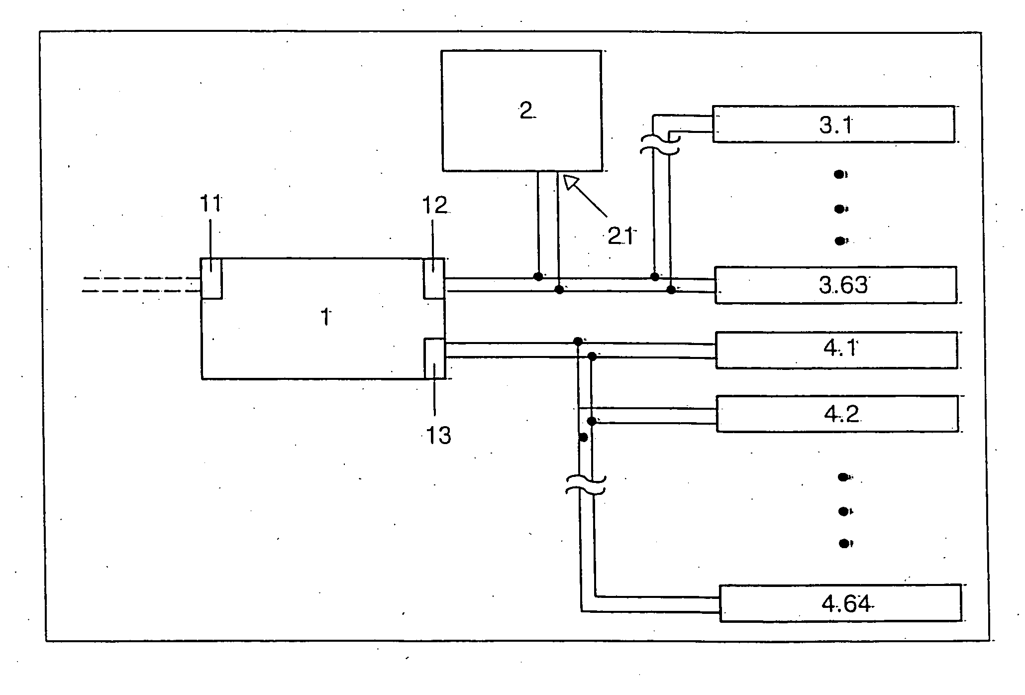
[0007] Via its data input, the data converter according to the invention can be controlled by the central control device in the same way as a lamp operating means. This means, in particular, that the data converter according to the invention can be subjected by the central control device to the same control signals as the lamp operating means controlled directly by the central control device. The evaluation unit of the data converter converts these control signals of the central control device into commands for controlling the lamp operating means controlled by the data converter. The data converter according to the invention behaves toward the central control device like a single lamp operating means with regard to addressing and control. On the other hand, however, the data output of the data converter according to the invention is designed in such a way that commands can be relayed via this data output to a large number of lamp operating means for controlling and monitoring their functions, these commands being generated by the evaluation unit of the data converter according to the invention as a function of the control signals of the central control device. It is possible in this way to enlarge the number of the lamp operating means in the lighting system whose function can be controlled by means of the central control device. The maximum permissible interface current of the central control device is not exceeded, since the data converter according to the invention behaves toward the central control device like a lamp operating means, and itself provides at its data output the interface current for the lamp operating means controlled by the data converter.
[0012] In accordance with a second preferred operating mode of the data converter, the control signals output by the central control device are received and evaluated by the lamp operating means via the data converter, in accordance with a group membership of the lamp operating means monitored by the data converter. The second operating mode permits the expansion of the grouping of the lamp operating means to a larger number of lamp operating means than could be operated solely with the aid of the central control device.
[0015] The data converter according to the invention is preferably capable of detecting the type of the lamp operating means connected to its data output. As a result, the data converter can evaluate queries from a central control device concerning the properties of the lamp operating means, and can answer them for the lamp operating means controlled by it. The data converter preferably answers queries from a central control device concerning the properties of the lamp operating means for the lamp operating means connected to the data output of the data converter with a prescribed standard value for the respective interrogated property of the lamp operating means when the lamp operating means controlled by the data converter differ from one another with reference to the respective interrogated property. The standard value is advantageously selected such that it is compatible with all types of lamp operating means. This ensures that the central control device does not react with a fault signal because of a missing acknowledgement of its query. When, however, the lamp operating means controlled by the data converter are identical with reference to the respective interrogated property, the abovenamed queries from the central control device for the lamp operating means connected to the data output of the data converter are preferably answered by the data converter with a reference value for the respective interrogated property, the data converter using as reference value the value of the respective interrogated property of a lamp operating means, selected by the data converter, of the lamp operating means connected to its data output. In other words, the data converter selects one of the lamp operating means controlled by it as reference unit for one or more properties, for example for the maximum dimming range, and acknowledges the value thereof for this property or properties to the central control device. In this case, the abovenamed queries from the central control device can be answered correctly by the data converter for the lamp operating means controlled by it.

Problems solved by technology

A disadvantage of the lighting systems whose central control devices communicate with the lamp operating means in accordance with the DALI protocol is that their address store is limited to sixty-four individual addresses and sixteen group addresses.
The maximum number of the lamp operating means that can be connected to the central control device is thereby correspondingly limited.

Method used


Image

  • Data converter for a lighting system, and method for operating a lighting system
  • Data converter for a lighting system, and method for operating a lighting system
  • Data converter for a lighting system, and method for operating a lighting system

Examples


Embodiment Construction

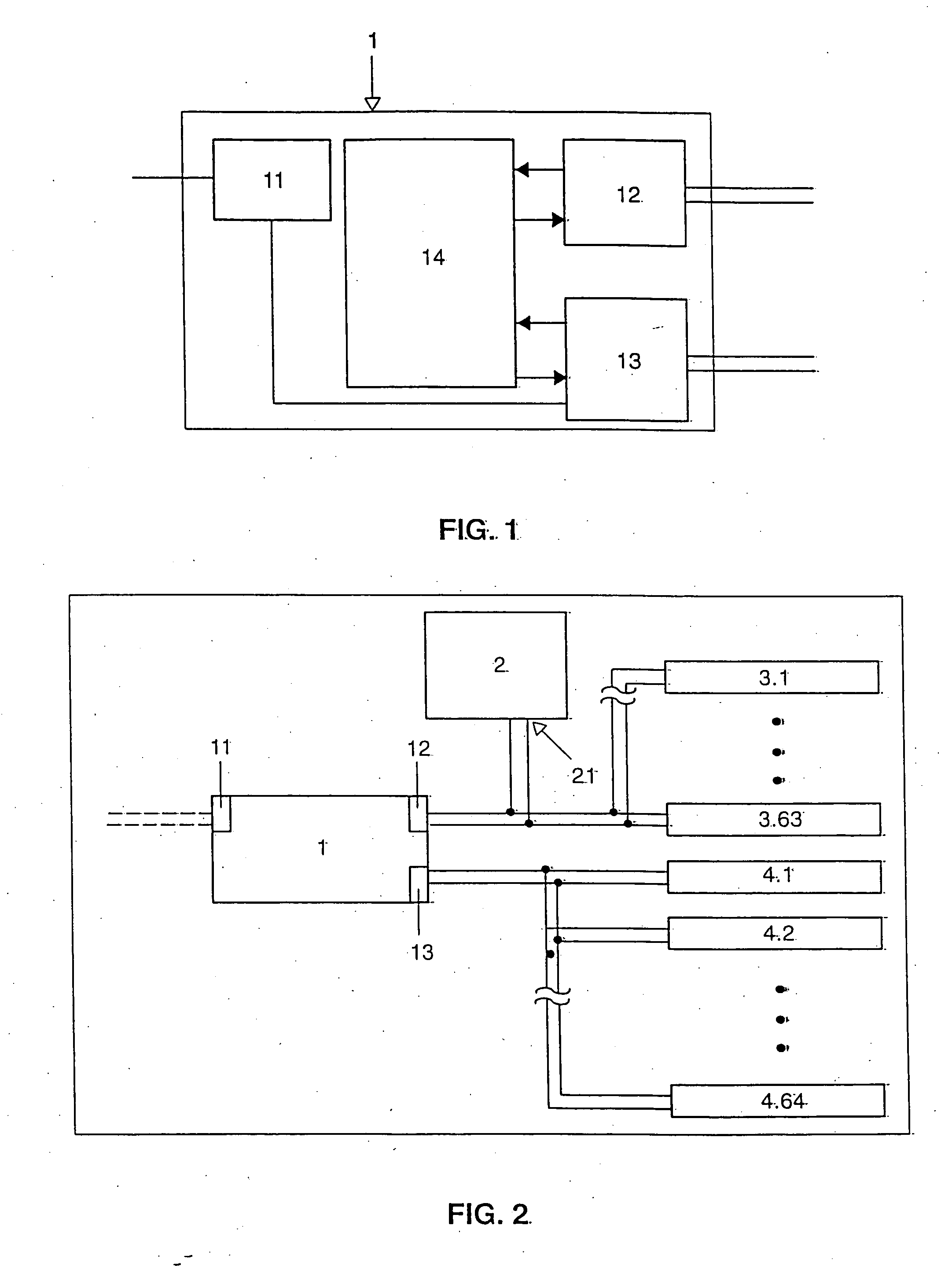
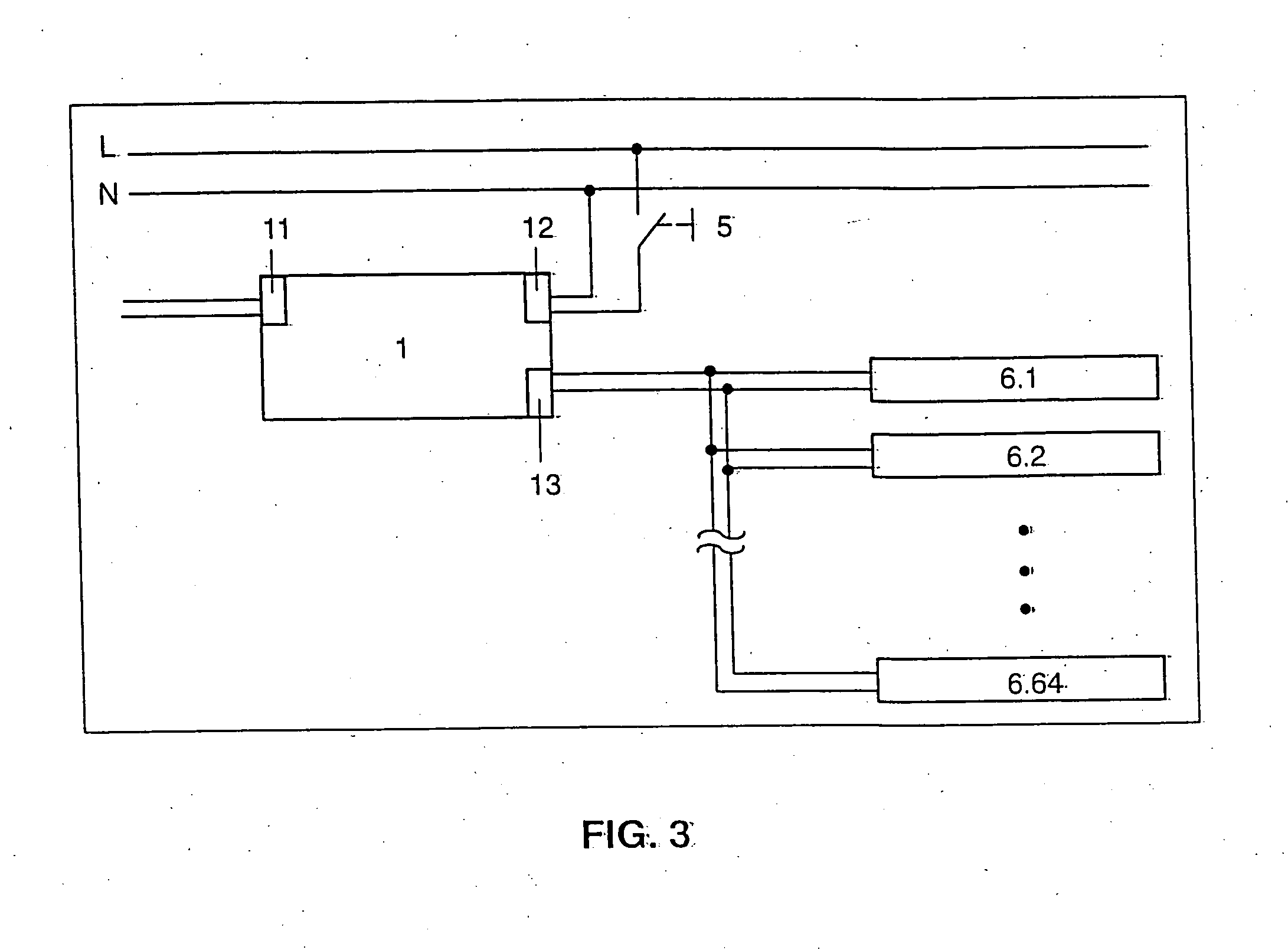
[0020] The function blocks of the data converter are depicted schematically in FIG. 1. The data converter 10 has a power supply unit 11 that can be connected to the line voltage, and supplies the data converter with electric energy. Moreover, the data converter 10 has a data input 12 that can be connected to an output of a central control device of a lighting system, and a data output 13 that can be connected to a multiplicity of lamp operating means. The data received at the data input 12 are evaluated by the downstream evaluation unit 14 of the data converter 10, and converted into commands for the lamp operating means connected to the data output 13. The evaluation unit 14 is designed as a programmable microcontroller. Via the data output 13, the power supply unit 11 provides the interface current for the communication with the lamp operating means connected to the data output 13. Both the communication of the data converter 10 with the central control device via the data input 1...


PUM


Abstract

A data converter for a lighting system, has a data input for the data converter to communicate with a central control device of the lighting system, a data output for the data converter to communicate with lamp operating elements, and an evaluation unit for evaluating the data received from the central control device and for controlling and monitoring the functions of the lamp operating elements. The data converter permits an enlargement of the number of the lamp operating elements, in the lighting system, that can be monitored by the central control device.

Description

I. TECHNICAL FIELD [0001] The invention relates to a data converter for a lighting system and to an operating method for a lighting system. II. BACKGROUND ART [0002] Laid-open application WO 02 / 41671 A2 describes a lighting system having a number of lamp operating means and a central control device for the lamp operating means, the lamp operating means having addressable interfaces via which digital data are communicated to the central control device. This communication is performed in accordance with the standardized so-called DALI protocol. The abbreviation DALI stands for Digital Addressable Lighting-Interface. [0003] A disadvantage of the lighting systems whose central control devices communicate with the lamp operating means in accordance with the DALI protocol is that their address store is limited to sixty-four individual addresses and sixteen group addresses. Moreover, the maximum current carrying capacity of the interface of the central control device is only 250 mA. The ma...

Claims


Application Information

Patent Timeline
IPC IPC(8): H05B37/02
CPCH05B37/0254H05B47/18
Inventor PILZ, AXEL
Owner PATENT TREUHAND GESELLSCHAFT FUR ELECTRIC GLUEHLAMPEN MBH
Learn More