
Method for fringe field compensation of an actively shielded superconducting nmr magnet

a superconducting magnet and active shielding technology, applied in the direction of superconducting magnets/coils, using reradiation, magnetic materials, etc., can solve the problems of deterioration of fringe field compensation and insufficient utilization of possible fringe field reduction of magnets, so as to facilitate the planning of buildings and utilization

Inactive Publication Date: 2005-03-31
BRUKER BIOSPIN
View PDF5 Cites 5 Cited by
  • Summary
  • Abstract
  • Description
  • Claims
  • Application Information

AI Technical Summary

Benefits of technology

This patent describes how to make sure that magnetic resonance imaging (MRI) machines have accurate readings when they are used on patients. It does this by measuring the extra electromagnetic effect created by differences between individual parts of the machine called dipoles. By adjusting these measurements, it ensures that the MRI machine produces consistent results no matter what kind of patient it has. This makes it easier to plan building spaces for these machines and also allows them to work more efficiently in places where there may not always be much room available.

Problems solved by technology

The technical problem addressed in this patent relates to how to optimize the fringe field of actively shielded magnets in a way that allows them to meet the requirements for safe usage in a laboratory setting while still allowing for efficient cooling and compact design. Additionally, there is a possibility of errors occurring during production and assembly of these magnets, leading to further variation in fringe field levels. The goal of the patent is to provide a solution for accurately compensating for these errors and ensuring optimal performance of the magnets.

Method used


Image

  • Method for fringe field compensation of an actively shielded superconducting nmr magnet
  • Method for fringe field compensation of an actively shielded superconducting nmr magnet
  • Method for fringe field compensation of an actively shielded superconducting nmr magnet

Examples


case 1

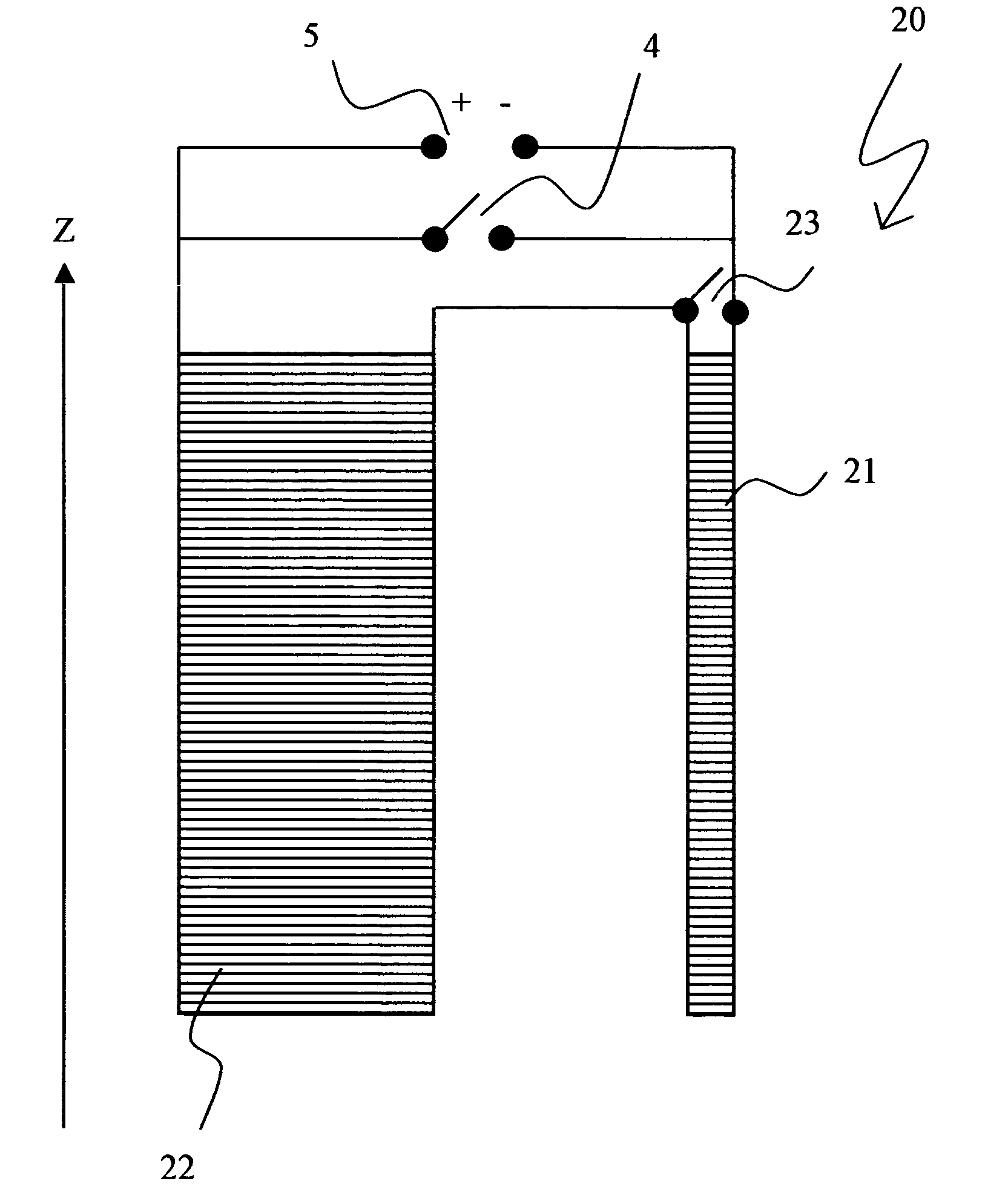
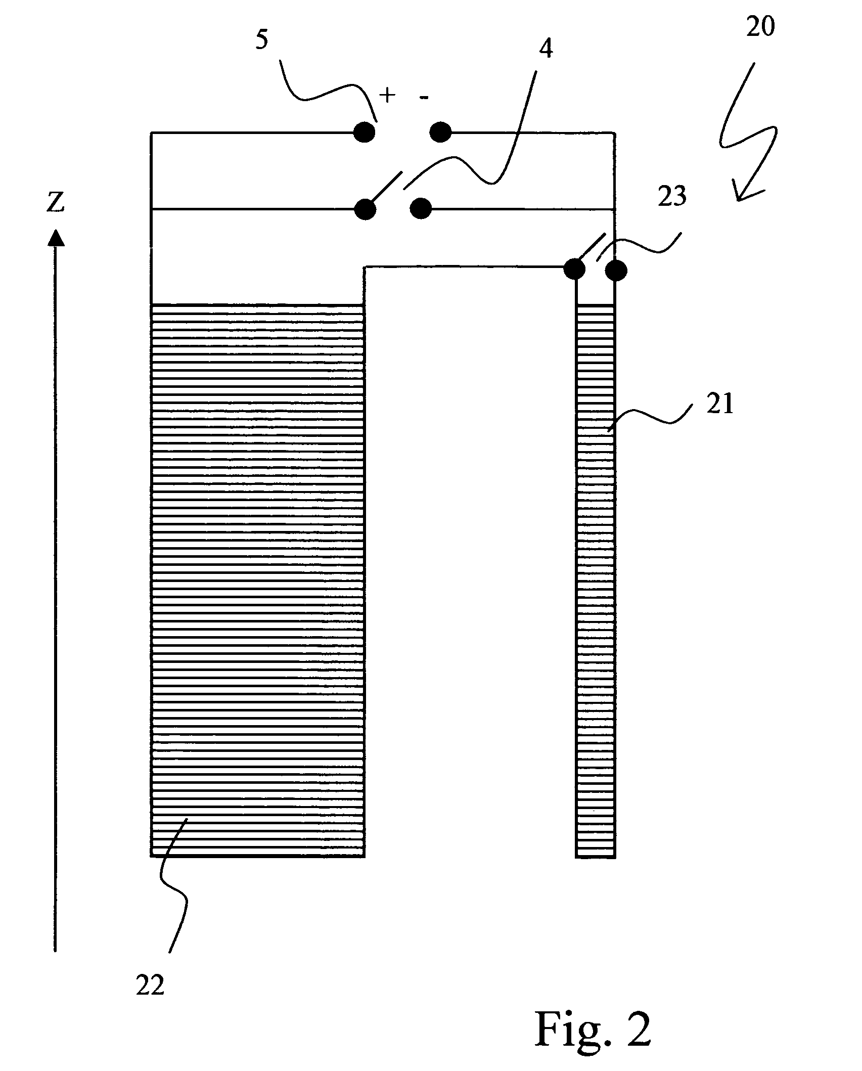
ditional dipole moment of the overall system which is caused by production tolerances and which is determined from the fringe field measurement, is positive. If the first partial region 21 (shielding portion) is short-circuited at the right time and the magnet coil arrangement 20 is further charged, an additional current is induced in the short-circuited first partial region 21 which increases its negative dipole moment to such an extent that, when the end field B has been reached, the additional dipole moment caused by production tolerances is eliminated in cooperation with the direct influence of the second partial region 22 on the dipole moment.

case 2

ditional dipole moment of the overall system which is caused by production tolerances and is determined from the fringe field measurement is negative. In this case, the target field B must be swept and the first partial region 21 must then be short-circuited. If the remaining magnetic coil arrangement 20 is discharged, an additional current is induced in the short-circuited first partial region 21 which reduces the negative dipole moment in this partial region to such an extent that the additional dipole moment caused by production tolerances is eliminated in cooperation with the direct influence of the second partial region 22 on the dipole moment after the end field B has been reached.

If, during subdivision of the partial regions, the first partial region which consists of the shielding portion, is also associated with a region of the main field portion, the inductive coupling between these two partial regions may also become positive. In this case, the above-described cases 1 an...


PUM


Abstract

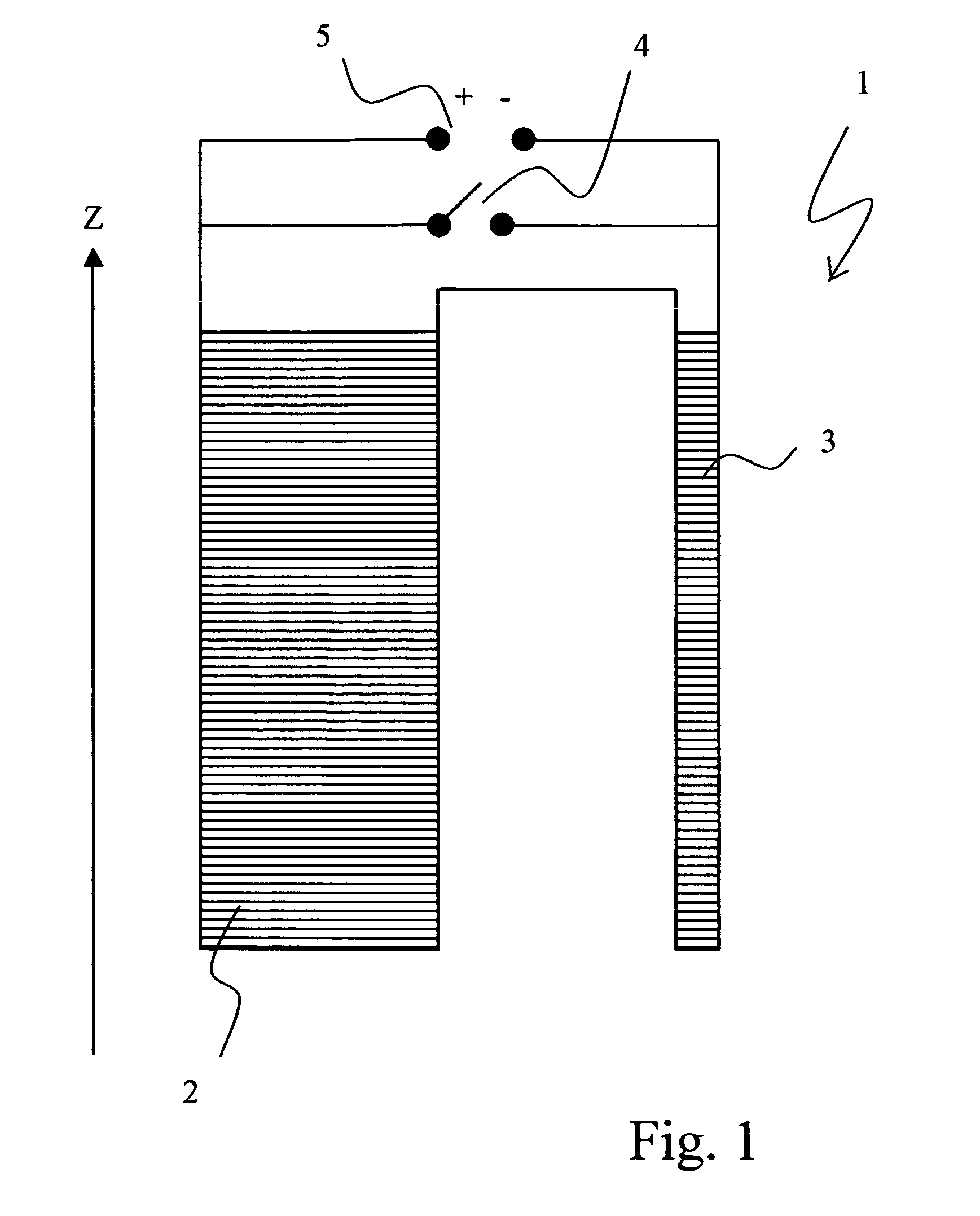
The invention concerns a method for charging an actively shielded magnet coil arrangement (20) comprising a first partial region (21) which can be superconductingly short-circuited using an additional switch (23), and a second partial region (22), wherein the two partial regions (21, 22) generate dipole moments of different signs. The magnetic fringe field B* is measured close to the desired operating state of the arrangement (20) and operating currents are determined for each of the two partial regions (21, 22) at which the overall magnetic field B is free from an additional dipole moment caused by production tolerances to permit setting of the theoretically optimum fringe field, irrespective of production tolerances. These operating currents are adjusted taking into consideration the inductive coupling between the partial regions (21, 22) through initially charging the entire magnet coil arrangement (20) and, after closing the additional switch (23), through continuation of the charging process in the second partial region (22) only. This eliminates deviations, which are caused by production tolerances, from the optimum theoretical fringe field of the arrangement (20) in a simple and inexpensive manner.

Description


Claims


Application Information

Patent Timeline
Owner BRUKER BIOSPIN
Learn More