Surface construction audit trail and manipulation

a technology of surface construction and audit trail, applied in the field of cad applications and geographic information systems, can solve the problems of not providing the geometric precision that many engineers require, not providing the traditional gis system with geometric precision, and still building databases on points, lines, and polygons

Active Publication Date: 2005-03-31
AUTODESK INC
View PDF53 Cites 25 Cited by
  • Summary
  • Abstract
  • Description
  • Claims
  • Application Information

AI Technical Summary

Benefits of technology

[0026] One or more embodiments of the invention provide a technique for managing the sequential operations involved in surface design and manipulation. The data additions and edits are remembered as a list of atomic operations. The user can browse the surface's operation list and togg...

Problems solved by technology

However, traditional GIS have been aimed at general cartography and broad land-use analysis, and not precision design for the construction and management of real-world projects.
In this regard, the geometric precision that many engineers require has not been provided by traditional GIS systems.
However, such databases are still built on points, lines, and polygons and cannot store geometric objects used in traditional CAD appl...

Method used


Image

  • Surface construction audit trail and manipulation
  • Surface construction audit trail and manipulation
  • Surface construction audit trail and manipulation

Examples


Embodiment Construction

[0035] In the following description, reference is made to the accompanying drawings which form a part hereof, and which is shown, by way of illustration, several embodiments of the present invention. It is understood that other embodiments may be utilized and structural changes may be made without departing from the scope of the present invention.

[0036] Hardware Environment

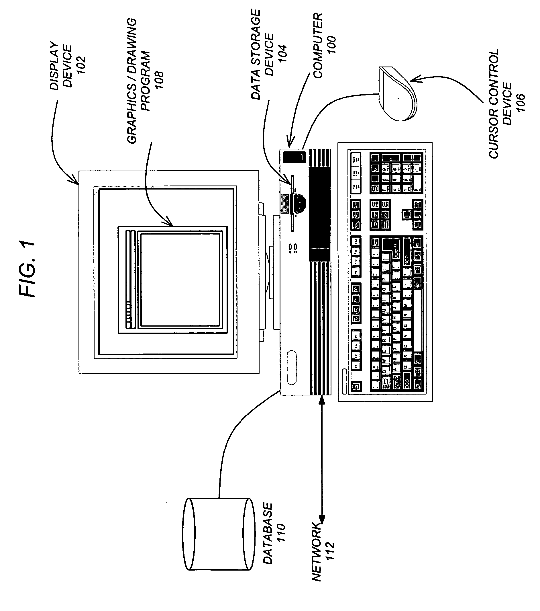
[0037]FIG. 1 is an exemplary hardware and software environment used to implement one or more embodiments of the invention. Embodiments of the invention are typically implemented using a computer 100, which generally includes, inter alia, a display device 102, data storage devices 104, cursor control devices 106, and other devices. Those skilled in the art will recognize that any combination of the above components, or any number of different components, peripherals, and other devices, may be used with the computer 100.

[0038] One or more embodiments of the invention are implemented by a computer-implemented grap...


PUM


Abstract

A method, apparatus, and article of manufacture provide the ability to manipulate a drawing surface in a CAD/GIS computer application. A drawing surface is displayed in a CAD/GIS application followed by the performance of a surface edit operation on the drawing surface. The surface edit operation is stored/saved as an atomic property in a list of surface edit operations. The list of surface edit operations is displayed in a graphical user interface (GUI). Each surface edit operation may be independently toggled on/off in the GUI and such toggling is reflected in the CAD/GIS application by displaying an effect of executing the surface edit operation if toggled on and displaying the drawing surface without execution of the surface edit operation if toggled off.

Description

CROSS-REFERENCE TO RELATED APPLICATIONS [0001] This application claims the benefit under 35 U.S.C. Section 119(e) of the following co-pending and commonly-assigned U.S. provisional patent application(s), which is / are incorporated by reference herein: [0002] Provisional Application Ser. No. 60 / 507,062, filed Sep. 29, 2003, by Christopher Eric Putnam and Mark W. Anderson, entitled “PARCEL DESIGN AND PLANAR TOPOLOGY,” attorneys' docket number 30566.310-US-P1; [0003] Provisional Application Ser. No. 60 / 507,080, filed Sep. 29, 2003, by Sreenadha B. Godavarthy, John M. Lewis, Thomas M Inzinga, Edward James Connor, Robert Bruce Todd, Jr., and Christopher Eric Putnam, entitled “SURFACE PROCESSING,” attorneys' docket number 30566.311-US-P1; [0004] Provisional Application Ser. No. 60 / 506,975, filed Sep. 29, 2003, by Kumud Dev Vaidya, Michael C. Rogerson, and Bhamadipati S. Rao, entitled “HORIZONTAL ALIGNMENT PROCESSING,” attorneys' docket number 30566.312-US-P1; and [0005] Provisional Applica...

Claims


Application Information

Patent Timeline
IPC IPC(8): G06F17/00G06T17/40
CPCG06T2200/24Y10S715/964G06T2219/2021G06T19/20
Inventor LEWIS, JOHN M.TODD, ROBERT BRUCE JR.CONNOR, EDWARD JAMESPUTNAM, CHRISTOPHER ERIC
Owner AUTODESK INC
Why Eureka
Try Eureka