Method and device for measuring pupil distance

a technology of pupil distance and measuring device, which is applied in the field of methods and devices for measuring pupil distance, can solve the problems of difficult measurement of interpupillary distance, high cost, and complicated structure of the device for measuring interpupillary distance, and achieves easy measurement of pupil distance, stable measurement, and low cost.

Inactive Publication Date: 2005-03-31
ASAHI KOGAKU KOGYO KK
View PDF5 Cites 35 Cited by
  • Summary
  • Abstract
  • Description
  • Claims
  • Application Information

AI Technical Summary

Benefits of technology

The present invention is advantageous in that it provides a method and d

Problems solved by technology

However, such conventional devices for measuring the interpupillary distance (e.g., the PD meter and the measuring device provided in the refractive power measurement device) have complicated structures and are expensive.
One of problems of the measurement device disclosed in the above mentioned publication is that the subject is required to conduct the adjustment of the measurement device while holding the measurement device.
In such a case, the measurement device tends to become unstabl

Method used


Image

  • Method and device for measuring pupil distance
  • Method and device for measuring pupil distance
  • Method and device for measuring pupil distance

Examples


first embodiment

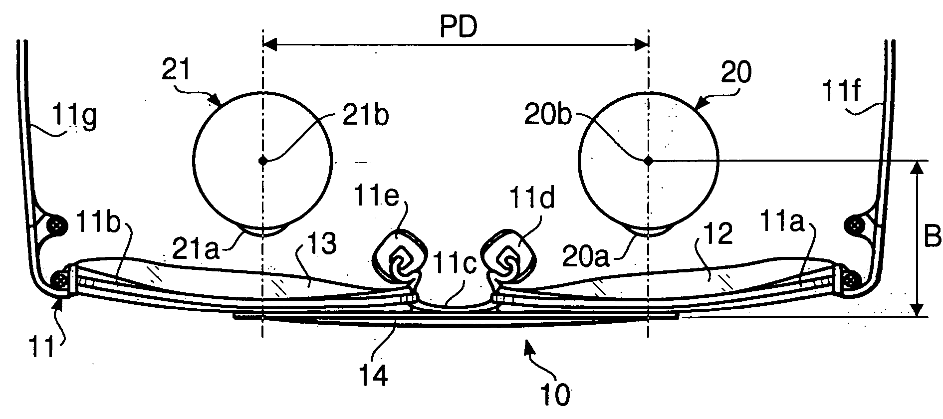
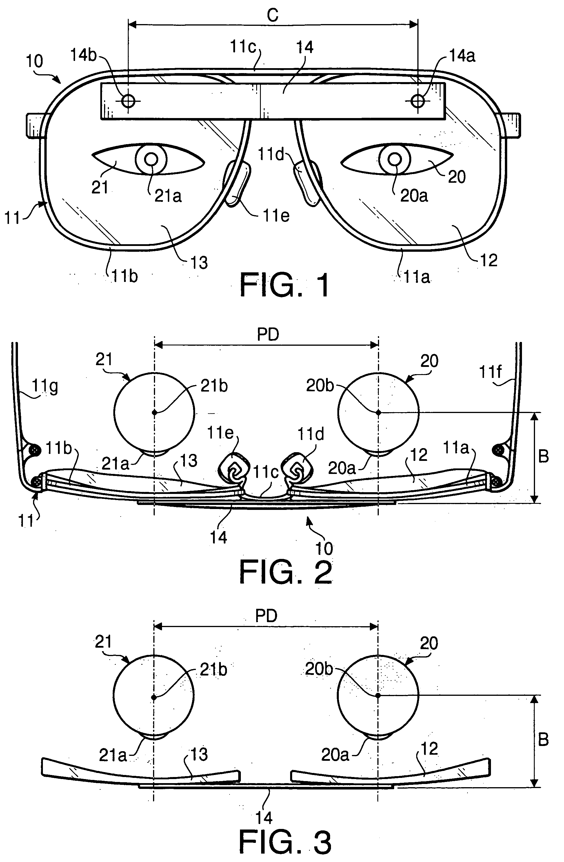
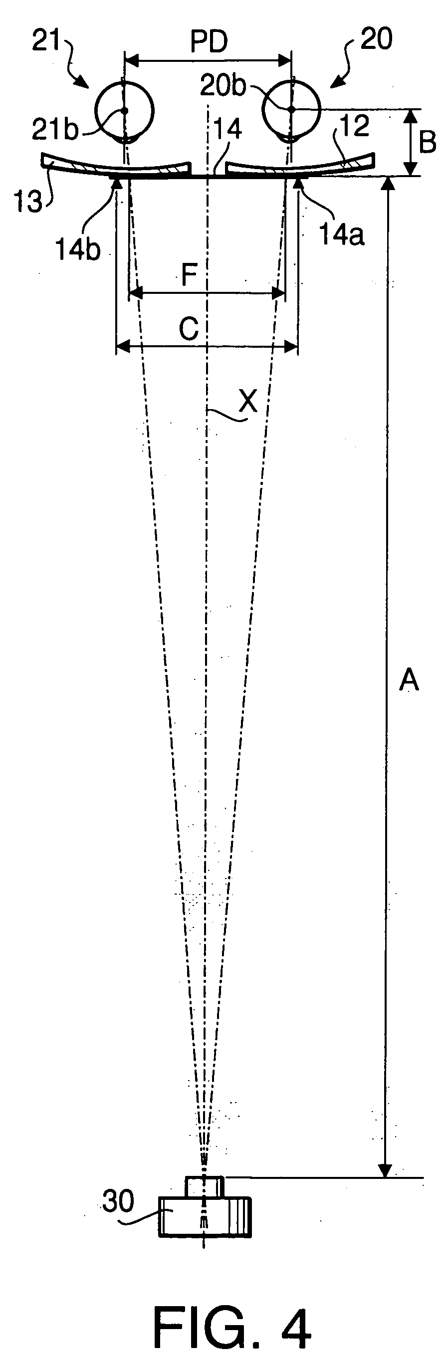
A method of measuring a pupil distance according to a first embodiment of the invention will be described. FIG. 1 is a front view of eyeglasses 10 with a scale used in the method of measuring the pupil distance according to the first embodiment. FIG. 2 is a plan view of the eyeglasses 10. The eyeglasses 10 have a frame 11, left and right lenses 12 and 13, and a scale 14 formed as a rectangular, plate member. The scale 14 is adhered to the left and right lenses 12 and 13 at the upper side of the lenses 12 and 13. As shown in FIG. 1, indicators 14a and 14b, each of which has a shape of a cross, are formed on the scale 14 at a distance C. FIG. 3 is a plan view of the eyeglasses 10 showing only eyes 20 and 21, the scale 14 and the lenses 12 and 13.

The frame 11 has rims 11a and 11b respectively supporting the lenses 12 and 13, a bridge 11c connected to the rims 11a and 11b, nose pads 11d and 11e, and temples 11f and 11g to be hooked to left and right ears.

It should be noted that the...

second embodiment

A method of measuring a pupil distance according to a second embodiment of the invention will be described. FIG. 8 is a front view of eyeglasses 40 with a scale used in the method of measuring the pupil distance according to the second embodiment.

The eyeglasses 40 have a frame 41, left and right lenses 42 and 43, and a scale 44 labeled with distance scale marks. The scale 44 is adhered to the left and right lenses 42 and 43 at the upper side of the lenses 42 and 43. In FIG. 8, to elements which are the same as those of the first embodiment, the same reference numbers are assigned, and the explanations thereof will not be repeated. Since the frame 41 has the same structure as that of the frame 11 of the first embodiment, the explanation of the frame 41 is not repeated. A plan view of the eyeglasses 40 is substantially the same as FIG. 2.

Various distances (A,B,F,FL and FR) defined in FIGS. 2 through 6 in the first embodiment are also used to describe the method according to the s...

third embodiment

A device for measuring a pupil distance according to a third embodiment will be described. FIG. 9 is a front view of a measuring device 50 according to the third embodiment. The measuring device 50 is used to measure the pupil distance. FIG. 10 is an enlarged view illustrating a sliding mechanism 60 of the measuring device 50. FIG. 11 is a cross sectional view of the sliding mechanism 60 taken along a line XI-XI in FIG. 10.

As shown in FIG. 9, the measuring device 50 includes a frame 51, left and right lenses 52 and 53 attached to the frame 51, a pair of aperture members 54 and 55 each of which has a form of a circular disc, and a pair of sliding mechanisms 60 and 70. The aperture member 54 is located at a position of an opening 52a formed on the lens 52 and has a circular hole 54a at the center thereof. The aperture member 55 is located at a position of an opening 53a formed on the lens 53 and has a circular hole 55a at the center thereof.

The sliding mechanism 60 supports the a...


PUM


Abstract

There is provided a method of measuring a pupil distance, which includes locating an imaging device at a position a predetermined distance away from a member attached to eyeglasses worn by a subject. The member has two indicators. The method further includes photographing the subject while the subject observes an observing point in the vicinity of the imaging device, measuring an apparent distance E between left and right pupils on a photographed image, and obtaining an interpupillary distance PD in accordance with PD=[(A+B)×C×E]/(A×D) where “A” represents a distance between the member and the imaging device, “B” represents a distance between a center of rotation and the member, “C” represents an actual distance between the indicators, and “D” represents an apparent distance between the indicators.

Description

BACKGROUND OF THE INVENTION The present invention relates to a method and a device for measuring a pupil distance including an interpupillary distance and a monocular pupil distance between a center line of a bridge of a nose of a subject and a pupil of each of left and right eyes of the subject. Eyeglasses and binocular magnifying glasses are configured such that optical axes of left and right lenses (left and right optical systems) for left and right eyes are located at pupil positions of a wearer. To determine a distance between left and right optical axes of the left and right lenses (or left and right optical system), it is required to measure an interpupillary distance of the user. The interpupillary distance is a distance between centers of pupils of left and right eyes measured when a person observes a distant, forward object. The interpupillary distance is equal to a distance between centers of rotation of left and right eyes. In general, a PD meter or a measurement devi...

Claims


Application Information

Patent Timeline
IPC IPC(8): A61B3/11
CPCA61B3/111A61B3/11
Inventor JOJIKI, MASAO
Owner ASAHI KOGAKU KOGYO KK
Why Eureka
Try Eureka