Head mount display

a display and display body technology, applied in the field of head mount displays, can solve the problems of poor visibility, unsolved problem of display mechanism provided on the upper part of the attachment member, and difficult to say that the design of the display body is excellent, and achieve the effects of secure the upper field of view of the user, excellent design, and enhanced outward appearan

Inactive Publication Date: 2011-02-24
SCALAR CORP
View PDF6 Cites 64 Cited by
  • Summary
  • Abstract
  • Description
  • Claims
  • Application Information

AI Technical Summary

Benefits of technology

[0014]Unlike the conventional cases, in the head mount display of the present invention, the display means and the light guide means align in the lateral direction during use as seen from the user. Therefore, the above-mentioned conventional problems caused by fore-and-aft alignment are solved. That is, the image projecting position of the light guide means is normally located close to the eye of the user, and the light guide means is provided at a position of each eyeglass lens when the attachment member is eyeglasses. The display means is provided while aligning in the lateral direction of the light guide means, and hence the display means is not provided on each of the upper parts of rims of an eyeglass frame. Thus, it is possible to avoid the situation that the display means is protrudingly provided on the upper part of the attachment member. The above-mentioned outward appearance of the head mount display during use is excellent in design, and it is possible to secure the upper field of view of the user.
[0015]The display means is attached, for example, between positions corresponding to those of eyeglass lenses of the attachment member. Attachment in this manner enables provision of the display means between both eyes of the user, whereby the display means completely disappears from the field of view of the user.
[0016]The display means may be attached on any of the front and rear of the attachment member. However, when the display means is attached on the rear of the attachment member, that is, attached thereto so as to be situated on a side of the user with respect to the attachment member when the user wears the attachment member, the display means can be hidden with the attachment member during use. With this, the outward appearance is further enhanced.
[0017]Examples of the available light guide means include a free-form surface prism in which the image is reflected therein by a predetermined number of times so as to be guided to the eye of the user. With use of the free-form surface prism, it is possible to easily achieve downsizing of the whole of the head mount display. Further, the light guide means is not limited to the free-form surface prism, and can be further downsized while maintaining the function of a light guide path for leading the image and a lens for enlarging the image even when being provided therewith. The light guide path may reflect the image by a predetermined number of times.

Problems solved by technology

With this configuration, the display mechanism is protrudingly provided on the upper part of the attachment member, and hence it is difficult to say that the design thereof are excellent.
Thus, even when the head mount display of Patent Document 1 is applied to the attachment-type HMD, the problem that the display mechanism is protrudingly provided on the upper part of the attachment member remains unsolved.
Thus, the problem of poor visibility also arises.

Method used


Image

  • Head mount display
  • Head mount display
  • Head mount display

Examples


Embodiment Construction

[0035]In the following, a preferred embodiment of the present invention is described in detail with reference to figures.

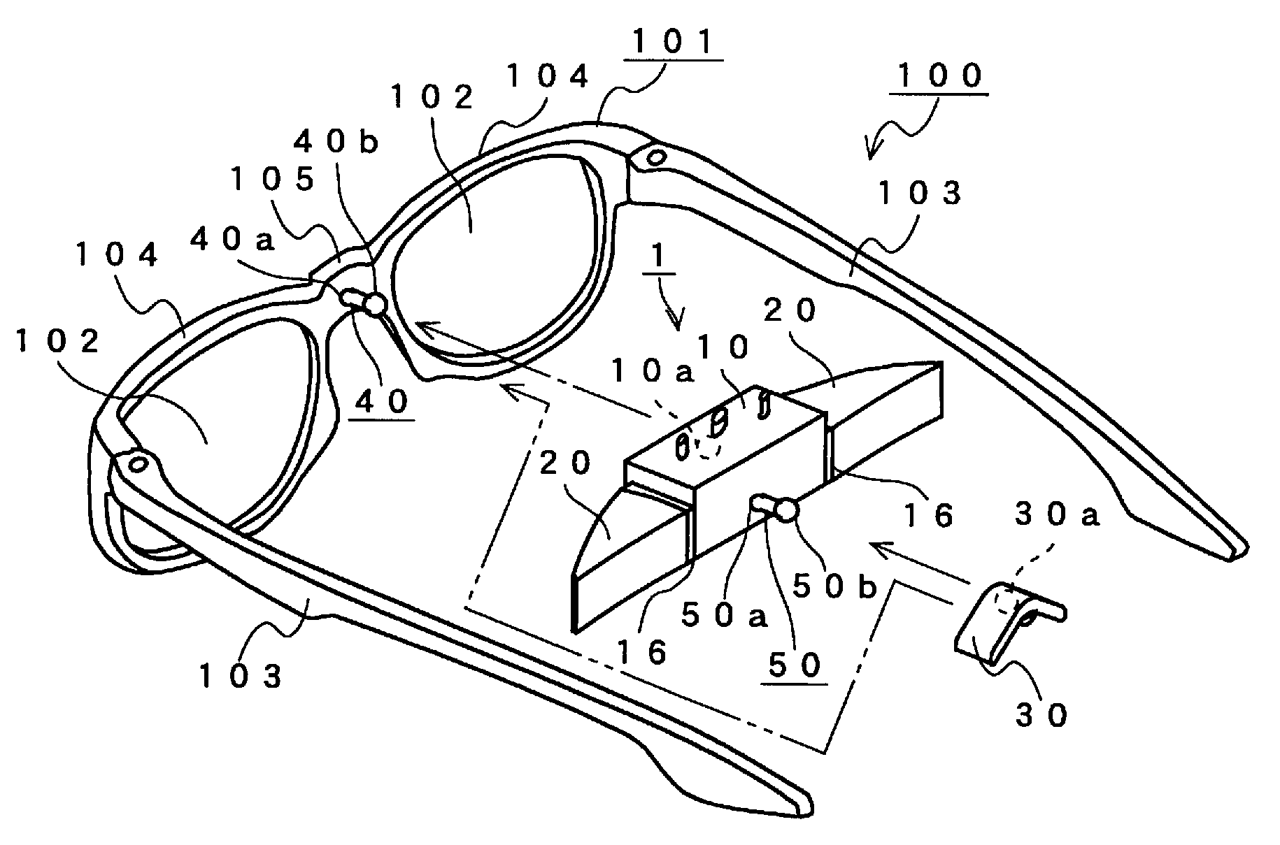
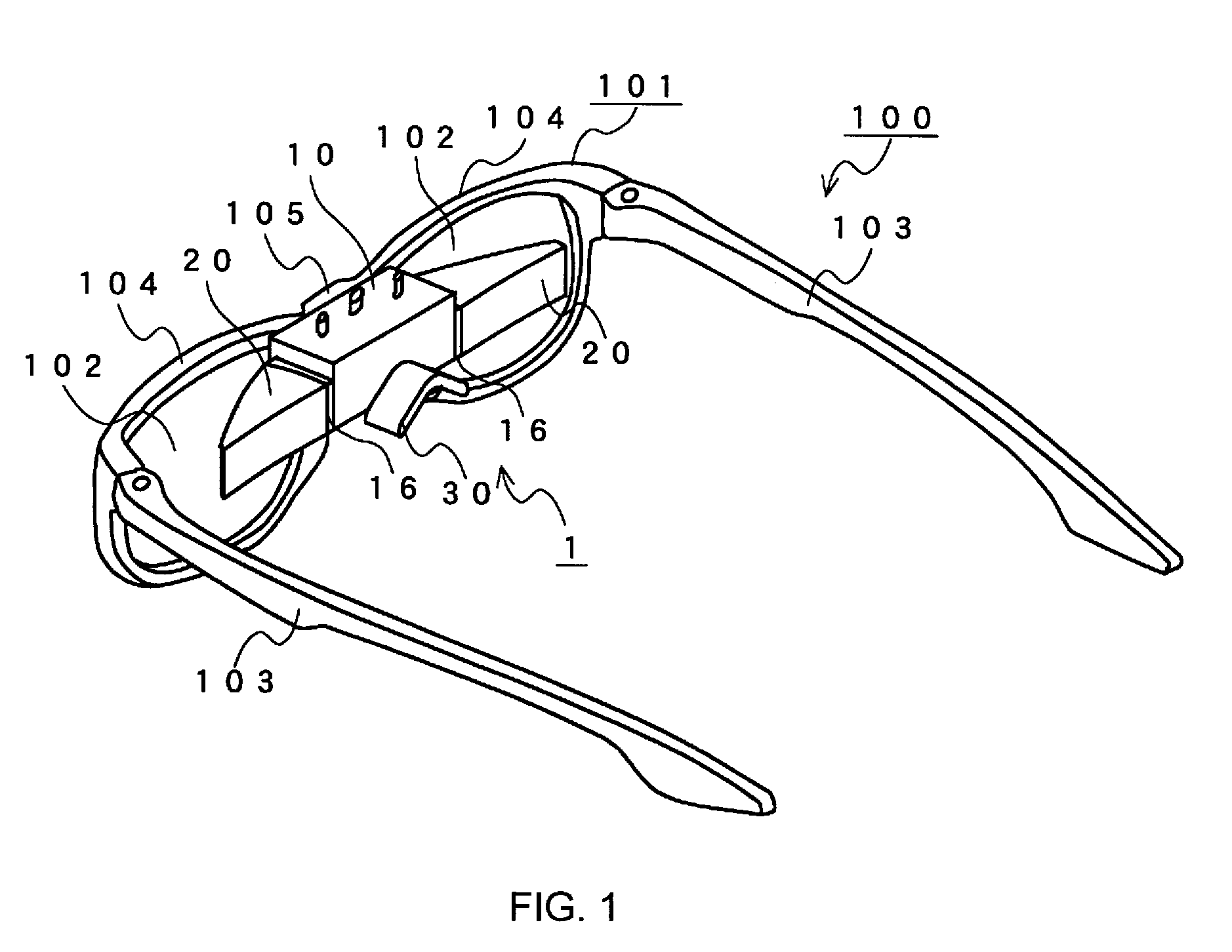
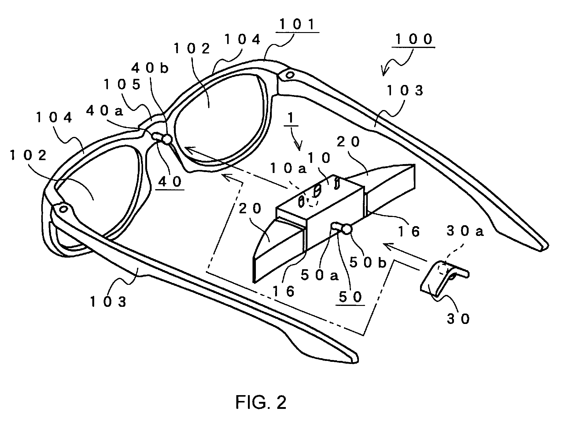
[0036]A head mount display 1 in this embodiment is an attachment-type HMD used while being attached to eyeglasses 100 having an eyeglass frame shape as illustrated in FIG. 1. In this embodiment, the head mount display 1 is attached on the rear of the eyeglasses 100. During use, the head mount display 1 is situated between a user and the eyeglasses 100. Therefore, those other than the user are less likely to find the presence of the head mount display 1. Note that, even when the head mount display 1 is provided in front of the eyeglasses 100, effects realized by the present invention are not prevented.

[0037]The eyeglasses 100 has the same structure as that of conventional pairs of eyeglasses, in which eyeglass lenses 102 are fitted to an eyeglass frame 101. The eyeglass frame 101 is provided with left and right temples 103, left and right rims 104, and a bridge 105...


PUM


Abstract

Provided is a head mount display of a type to be attached to eyeglasses. A head mount display (1) is provided with a case (10) incorporating displays, and free-form surface prisms (20). The head mount display (1) is used while the case (10) is attached to a bridge (105) of eyeglasses (100). When a user wears the eyeglasses (100), the case (10) incorporating displays and the free-form surface prisms (20) are connected to each other while aligning in a lateral direction as seen from the user.

Description

TECHNICAL FIELD[0001]The present invention relates to a head mount display used while being mounted to a user's head.BACKGROUND ART[0002]A head mount display, which is mounted to a part of a body such as a head during use, for displaying an image in front of the user's eyes, is used in various fields for displaying an image, which includes a field of virtual reality. Generally, the head mount display is formed into a goggle-like shape or into a large eyeglass-frame shape. Further, there is also available a head mount display of a type of being used while being attached to an attachment member having an eyeglass-frame shape (hereinafter, referred to as “attachment-type head mount display (HMD)”).[0003]Generally, it is preferred that the head mount display be as small as possible. In particular, the head mount display excellent in design has a size and a shape which are less bothersome for a user when being attached to the user's head.[0004]The attachment-type HMD allows, even during ...

Claims


Application Information

Patent Timeline
Patent Type & Authority Applications(United States)
IPC IPC(8): G09G5/00
CPCG02B6/00G02B27/0176G02B27/0172G02B7/12G02B27/01H04N5/64
Inventor YAMAMOTO, MASAO
Owner SCALAR CORP
Why Eureka
Try Eureka