Eye refractive power measurement apparatus

a technology of refractive power measurement and eye, which is applied in the field of eye refractive power measurement apparatus, can solve the problems of light becoming noise, measurement accuracy being sometimes contrarily lowered,

Inactive Publication Date: 2005-03-31
NIDEK CO LTD
View PDF6 Cites 41 Cited by
  • Summary
  • Abstract
  • Description
  • Claims
  • Application Information

AI Technical Summary

Benefits of technology

[0006] An object of the invention is to overcome the problems described above and to provide an eye refractive power measurement apparatus which is c

Problems solved by technology

However, in this case, corneal reflection or crystalline lens reflection of the projected measurement light tends to bec

Method used


Image

  • Eye refractive power measurement apparatus
  • Eye refractive power measurement apparatus
  • Eye refractive power measurement apparatus

Examples


Embodiment Construction

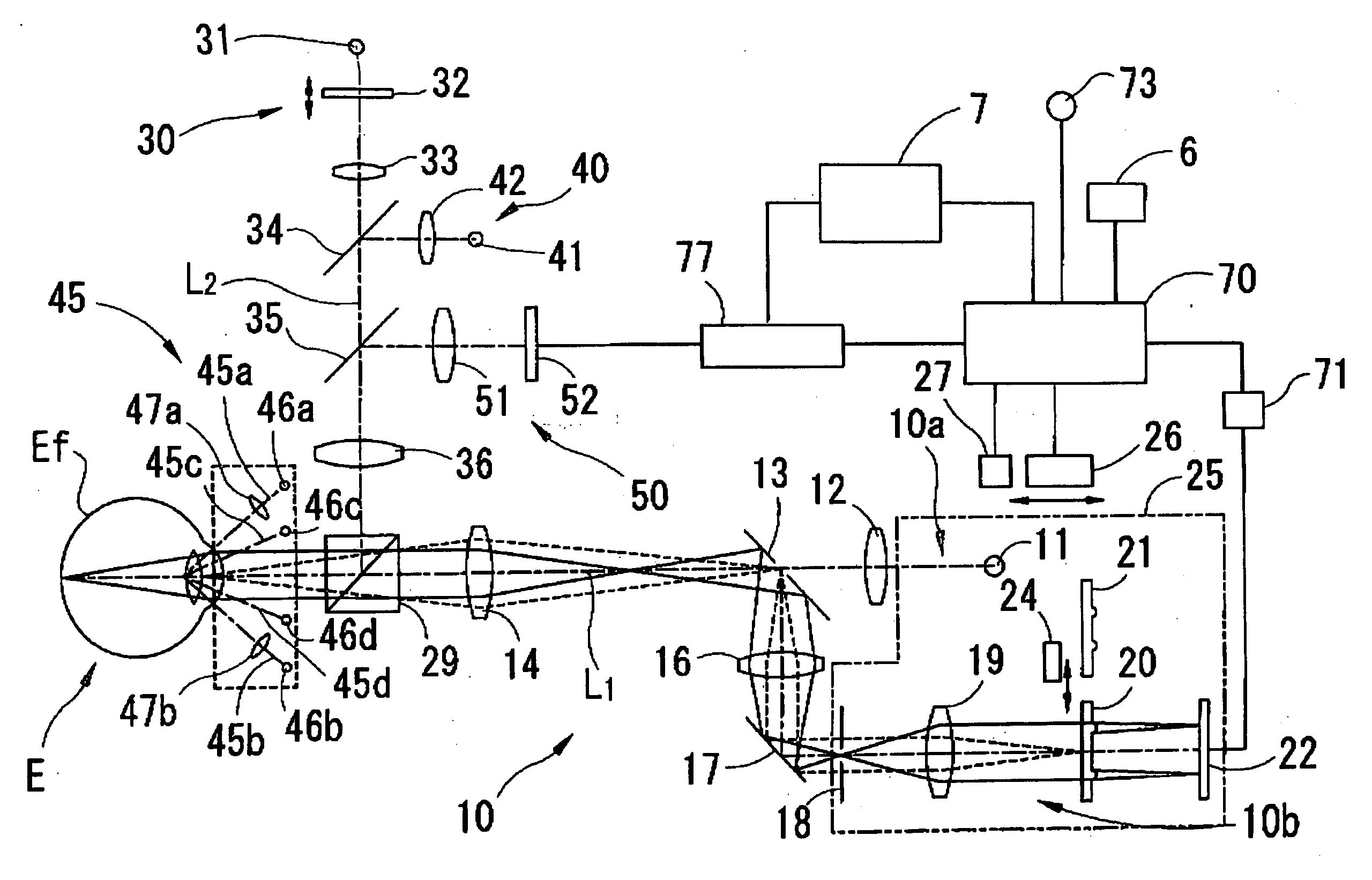
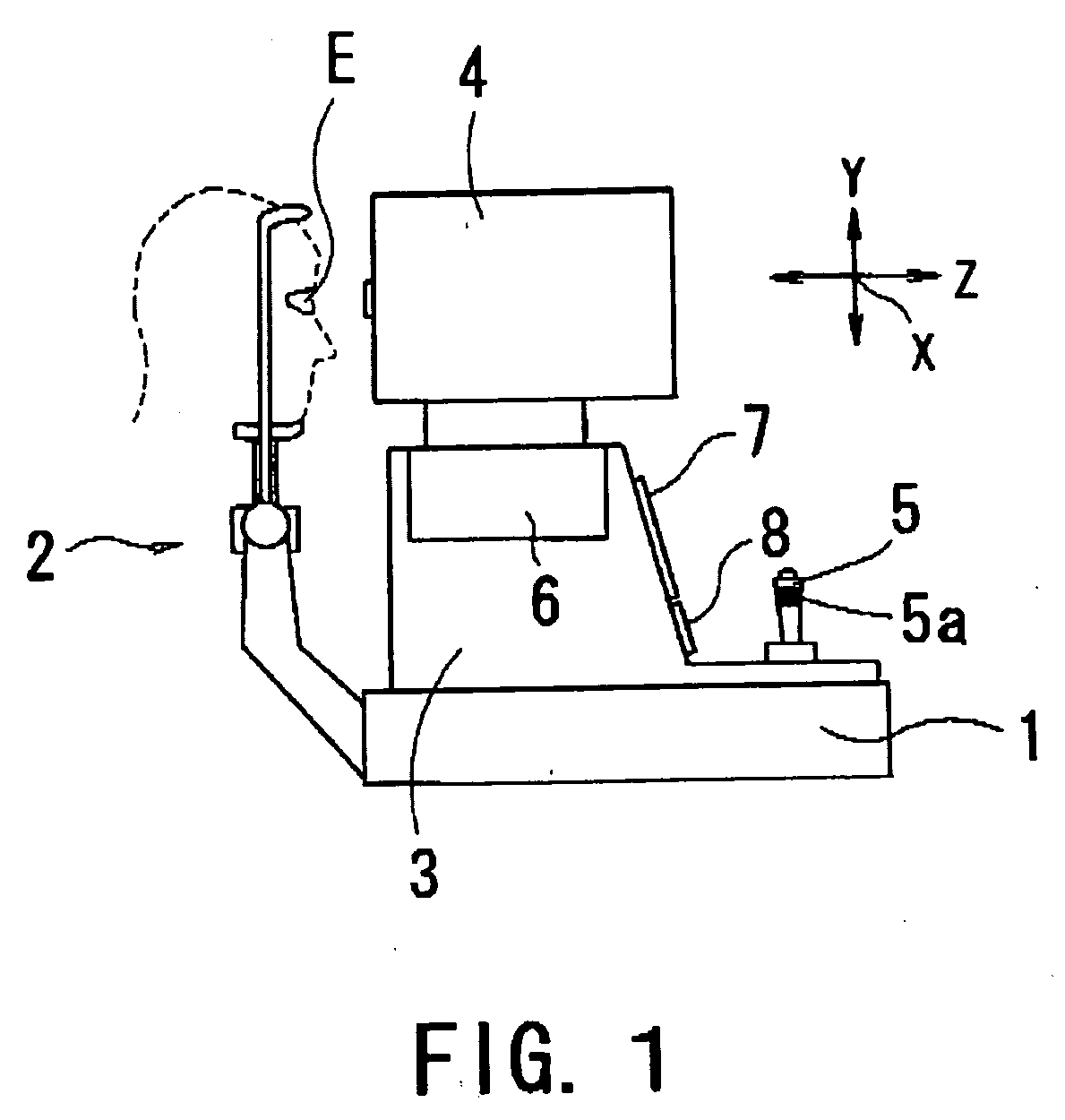
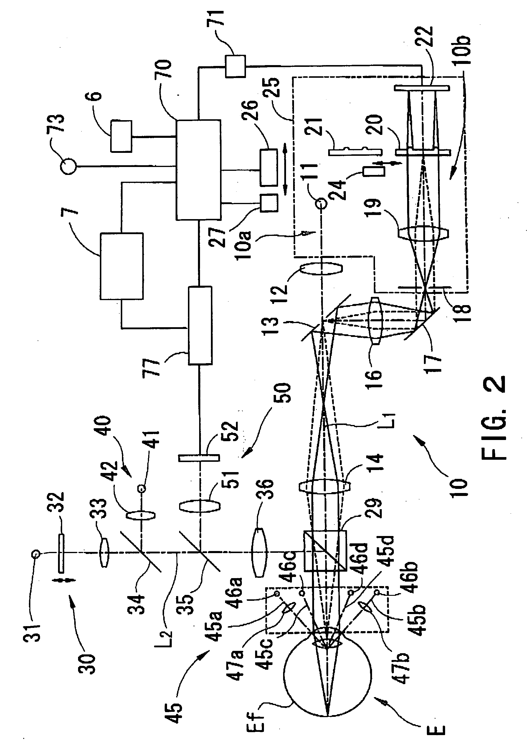
[0016] A detailed description of one preferred embodiment of an eye refractive power measurement apparatus embodied by the present invention is provided below with reference to the accompanying drawings. FIG. 1 is a view showing a schematic configuration of the eye refractive power measurement apparatus consistent with one embodiment of the present invention. The measurement apparatus is provided with a base 1, a face-supporting unit 2 being attached to the base 1, a mobile base 3 being provided movably on the base 1, and a measurement part 4 being provided movably on the mobile base 3 and storing optical systems described later. The measurement part 4 is moved in a right / left direction (an X-direction), an up / down direction (a Y-direction), and a back / forth direction (a Z-direction) with respect to an eye E of an examinee by an X-, Y- and Z-movement part 6 provided to the mobile base 3. The movement part 6 is constituted of a sliding mechanism, a motor, and the like which are provi...


PUM


Abstract

An eye refractive power measurement apparatus which is capable of measuring even an eye with a small pupil diameter and measuring a normal eye with a large enough pupil diameter with accuracy and stability. The apparatus includes a measurement optical system for photo-receiving measurement light from a fundus via a ring-shaped aperture arranged at an approximately conjugate position with a pupil by using a photodetector, a changing device for changing a size of the ring-shaped aperture on a pupillary surface to a size different in both inside diameter and outside diameter, and a calculation device for calculating the eye refractive power based on a photo-receiving result obtained by the photodetector.

Description

BACKGROUND OF THE INVENTION [0001] 1. Field of the Invention [0002] The present invention relates to an eye refractive power measurement apparatus for measuring eye refractive power of an eye of an examinee objectively. [0003] 2. Description of Related Art [0004] Conventionally, there is known an eye refractive power measurement apparatus which projects spot-shaped measurement light onto a fundus via a central pupillary portion and photo-receives reflection light from the fundus via a peripheral pupillary portion and a ring-shaped aperture (opening) which is arranged at an optically conjugate position with a pupil using a two-dimensional photodetector or the like to obtain eye refractive power based on a photo-receiving result thereof (see Japanese Patent Application Unexamined Publication No. Hei11-225963). In such an apparatus, in order to ensure measurement accuracy, the size of the ring-shaped aperture is set so as to photo-receive the reflection light from the fundus via a ring...

Claims


Application Information

Patent Timeline
IPC IPC(8): A61B3/103A61B3/10
CPCA61B3/103
Inventor HANEBUCHI, MASAAKIGONO, MITSUHIROKURACHI, MIKIOISOGAI, NAOKI
Owner NIDEK CO LTD
Why Eureka
Try Eureka