Perimeter

A technology of perimetry and field of vision, applied in the field of perimetry, can solve the problems that the background brightness and the brightness of the visual standard cannot be easily adjusted, and the size of the visual standard can not be easily adjusted

Inactive Publication Date: 2007-08-15
MATSUSHITA ELECTRIC WORKS LTD
View PDF2 Cites 21 Cited by
  • Summary
  • Abstract
  • Description
  • Claims
  • Application Information

AI Technical Summary

Problems solved by technology

However, in the above-mentioned traditional perimetry, since the visual target is projected on the screen, or light-emitting diodes are used to display the light-stimulating visual target, there is a problem that the background brightness, the visual target brightness and the visual target size cannot be easily adjusted.

Method used


Image

  • Perimeter
  • Perimeter
  • Perimeter

Examples


Embodiment Construction

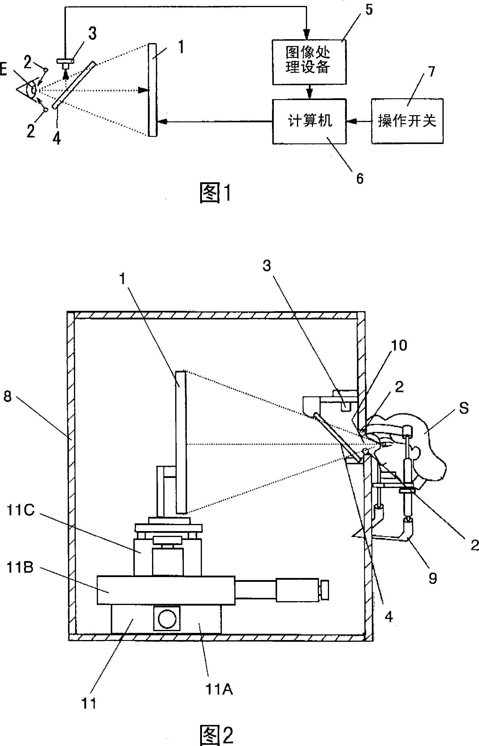
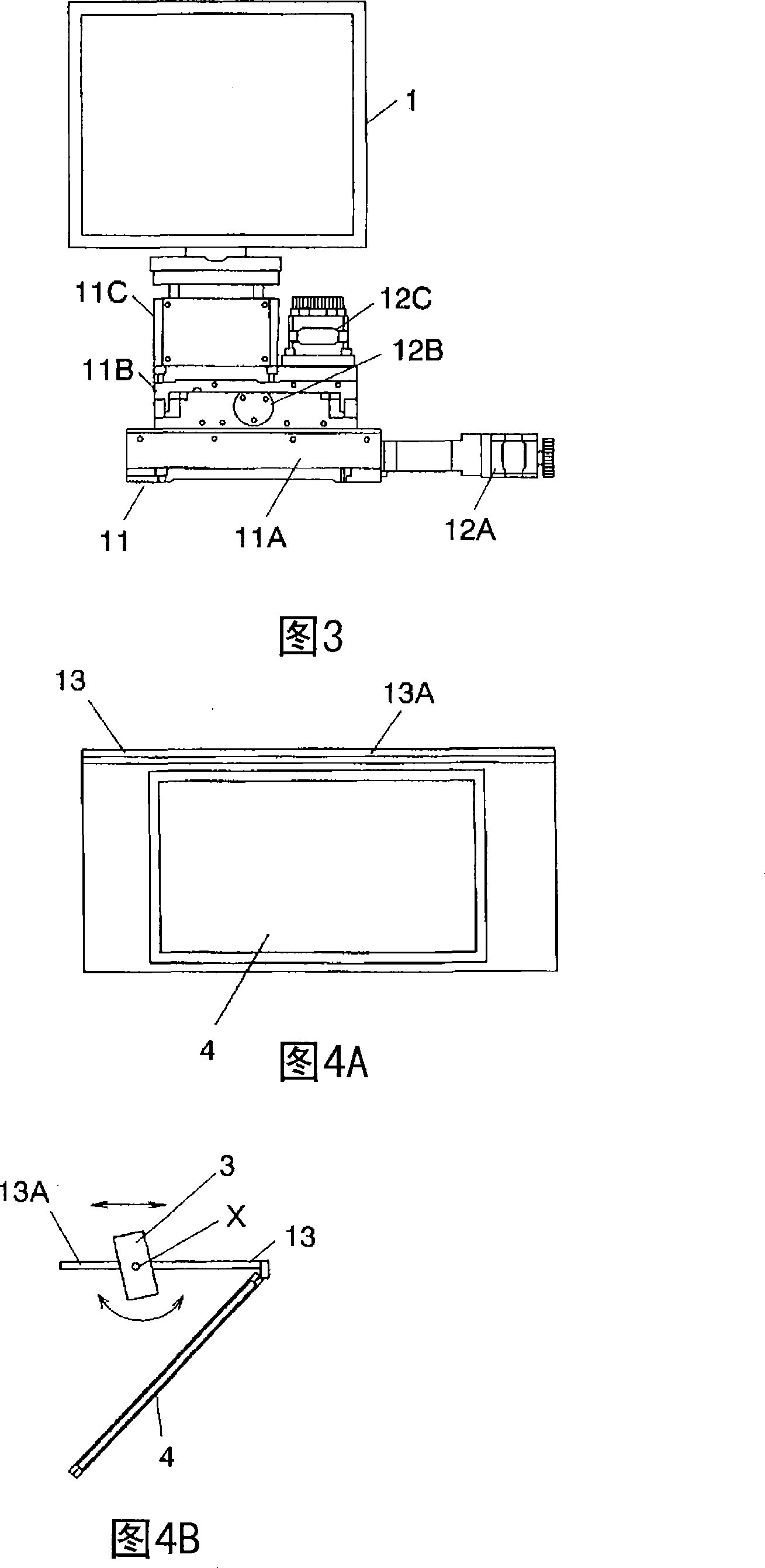
[0043] Hereinafter, the present invention will be described in detail with reference to the accompanying drawings. FIG. 1 is a schematic diagram showing the configuration of a perimeter meter of this embodiment. Perimeter includes: liquid crystal display 1 , infrared light emitting diode 2 , CCD camera 3 , one-way see-through glass 4 , image processing equipment 5 , computer 6 and operation switch 7 . As shown in FIG. 2 , a liquid crystal display 1 , an infrared light emitting diode 2 , a CCD camera 3 and a one-way see-through glass 4 are accommodated in a box-shaped casing 8 . There is a peephole 10 on one side of the casing 8, through which the examinee can see the liquid crystal display 1 installed in the casing 8; a jaw support base 9 is also installed on this side for supporting The subject's jaw.

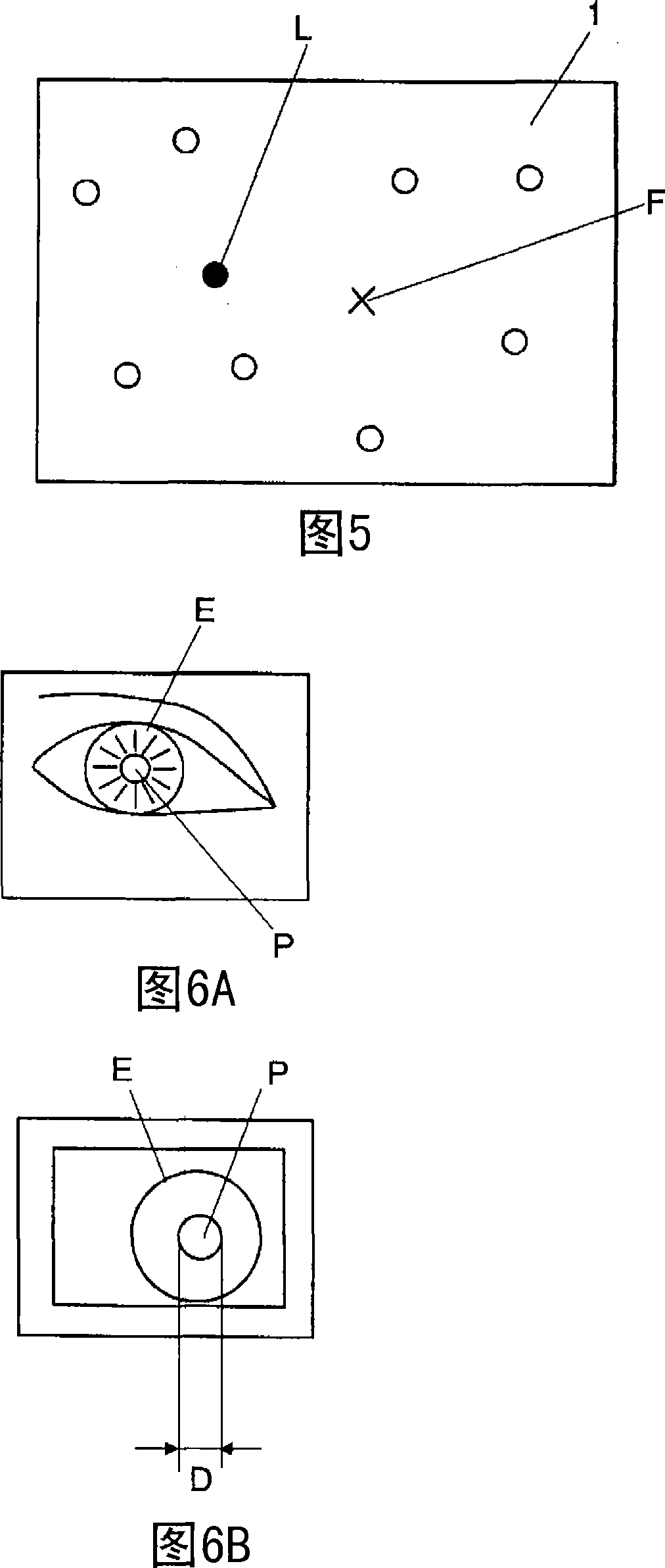
[0044] The liquid crystal display 1 (display device) displays a fixed optotype F for fixing the subject's line of sight and a photostimulation optotype L for providing photo...


PUM


Abstract

A diopsimeter comprises a display (1), an infrared light-emitting diode (2), a CCD camera (3), a half-silvered mirror (4), an image processing device (5), a computer (6), and an operation switch (7). The computer (6) displays a fixing target for fixing the line of sight of a subject and light stimulus targets for giving light stimulus to the pupil of the subject at predetermined positions of the display (1). The infrared light-emitting diodes (2) projects infrared radiation toward the eye ball of the subject. The CCD camera (3) images the eye ball of the subject by using the projected infrared radiation. The image processing device (5) detects the diameter of the pupil of the subject from captured image. The computer (6) measures the field of view from the variation of the detected pupil diameter. The characteristic point of the invention is that the display (1) is so constructed that the luminance of the background of the screen and the luminances of the light stimulus targets can be independently adjusted.

Description

technical field [0001] The invention relates to a perimetry for measuring the visual field of a subject. Background technique [0002] An examination of the visual field (ie, perimetry) is done to diagnose shrinkage of the visual field that is a symptom of diseases such as glaucoma. In traditional visual field measurement, the subject's visual field is measured by displaying an eye-target at a specific position in front of the subject's eyes, and then asking the subject to answer whether they see the target. This examination is a subjective examination based on the subject's subjective answer, and the subject's visual field range is determined by measuring the visual field multiple times while changing the display position of the optotype one by one. In such a subjective inspection, there is a problem in that the inspection result is easily affected by the physical condition, concentration, etc. of the examinee, and accurate inspection cannot be performed. In addition, sin...

Claims


Application Information

Patent Timeline
Patent Type & Authority Applications(China)
IPC IPC(8): A61B3/02
Inventor 田舍片悟村上宗司福岛省吾福永秀雄田渊昭雄可儿一孝前田史笃
Owner MATSUSHITA ELECTRIC WORKS LTD
Why Eureka
Try Eureka