Liquid delivery apparatus

a technology of liquid delivery apparatus and diaphragm, which is applied in the direction of positive displacement liquid engine, pump, machine/engine, etc., can solve the problems of inefficiency in complicated structure of the ink jet head, and achieve the effect of reducing the rigidity of the piezoelectric actuator plate and effectively increasing the displacement of the diaphragm

Active Publication Date: 2005-03-31
BROTHER KOGYO KK
View PDF3 Cites 29 Cited by
  • Summary
  • Abstract
  • Description
  • Claims
  • Application Information

AI Technical Summary

Benefits of technology

[0013] According to the apparatus, the piezoelectric layer is present at least at the position corresponding to the inner peripheral part of the pressure chamber, while the inner or second part of the piezoelectric layer positionally corresponding to a part of the pressure chamber on the inner side of the inner peripheral part may be a void, or formed of the second part having a thickness smaller than the first part of the

Problems solved by technology

However, the structure of this ink jet head is complicated.
Th

Method used


Image

  • Liquid delivery apparatus
  • Liquid delivery apparatus
  • Liquid delivery apparatus

Examples


first embodiment

[0025] First Embodiment

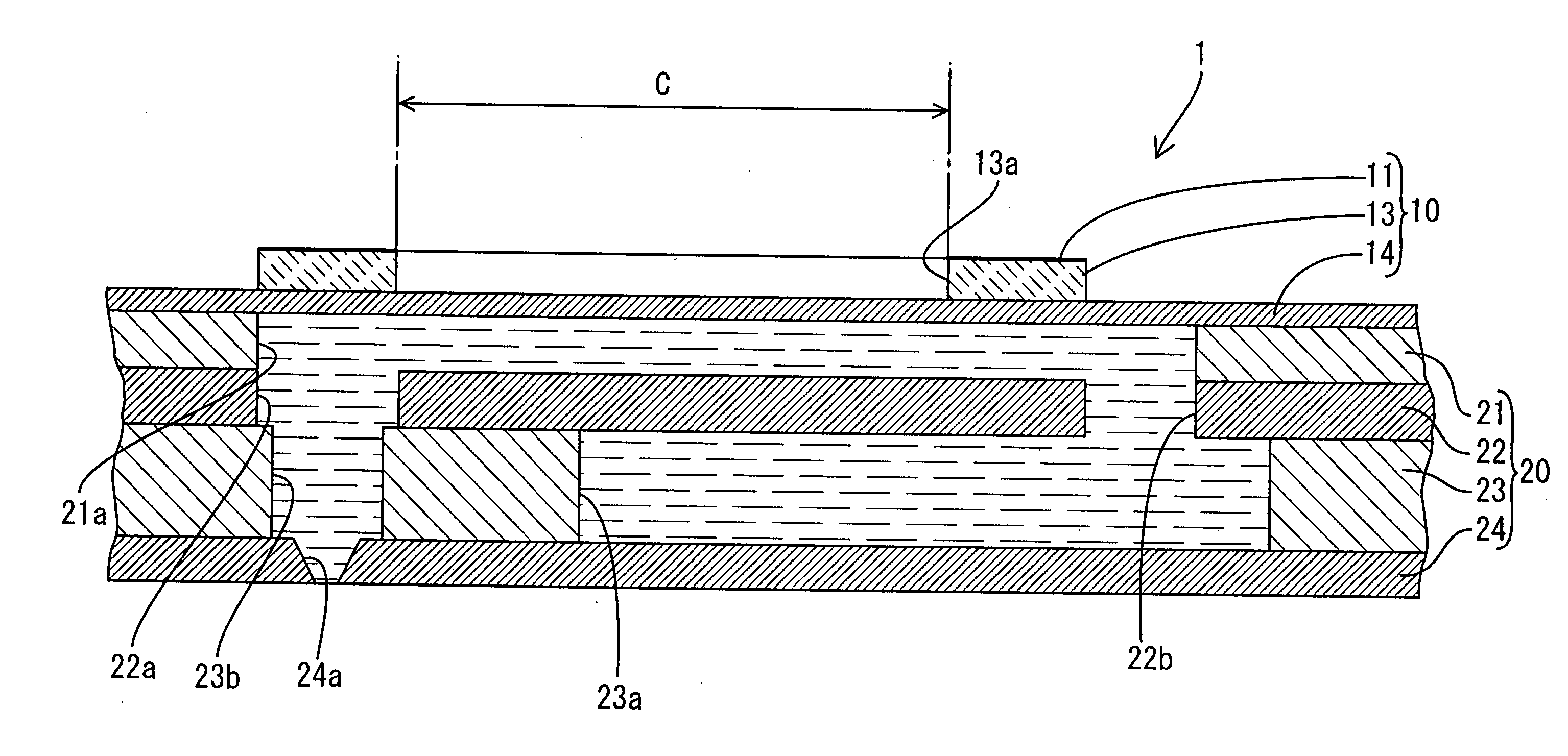
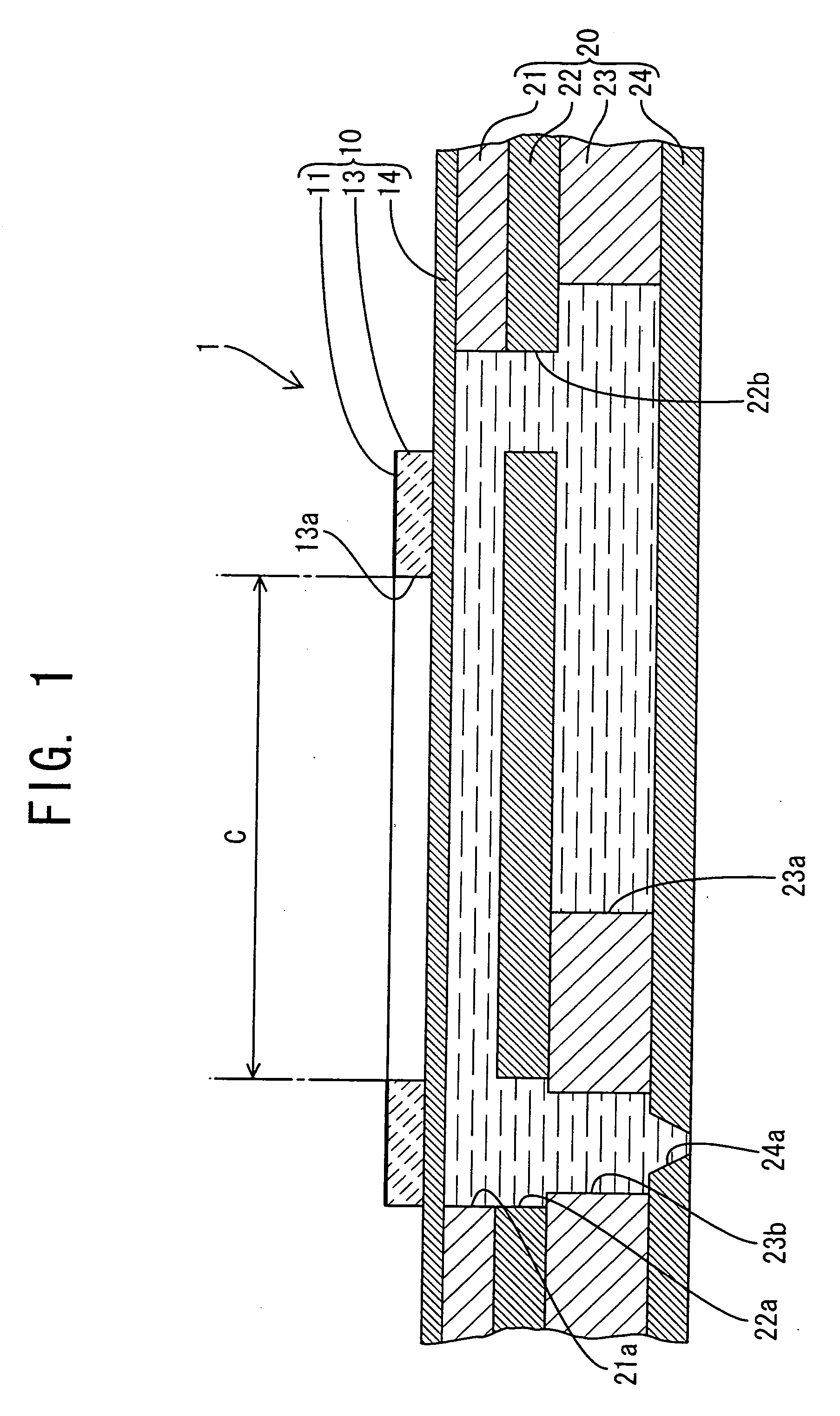
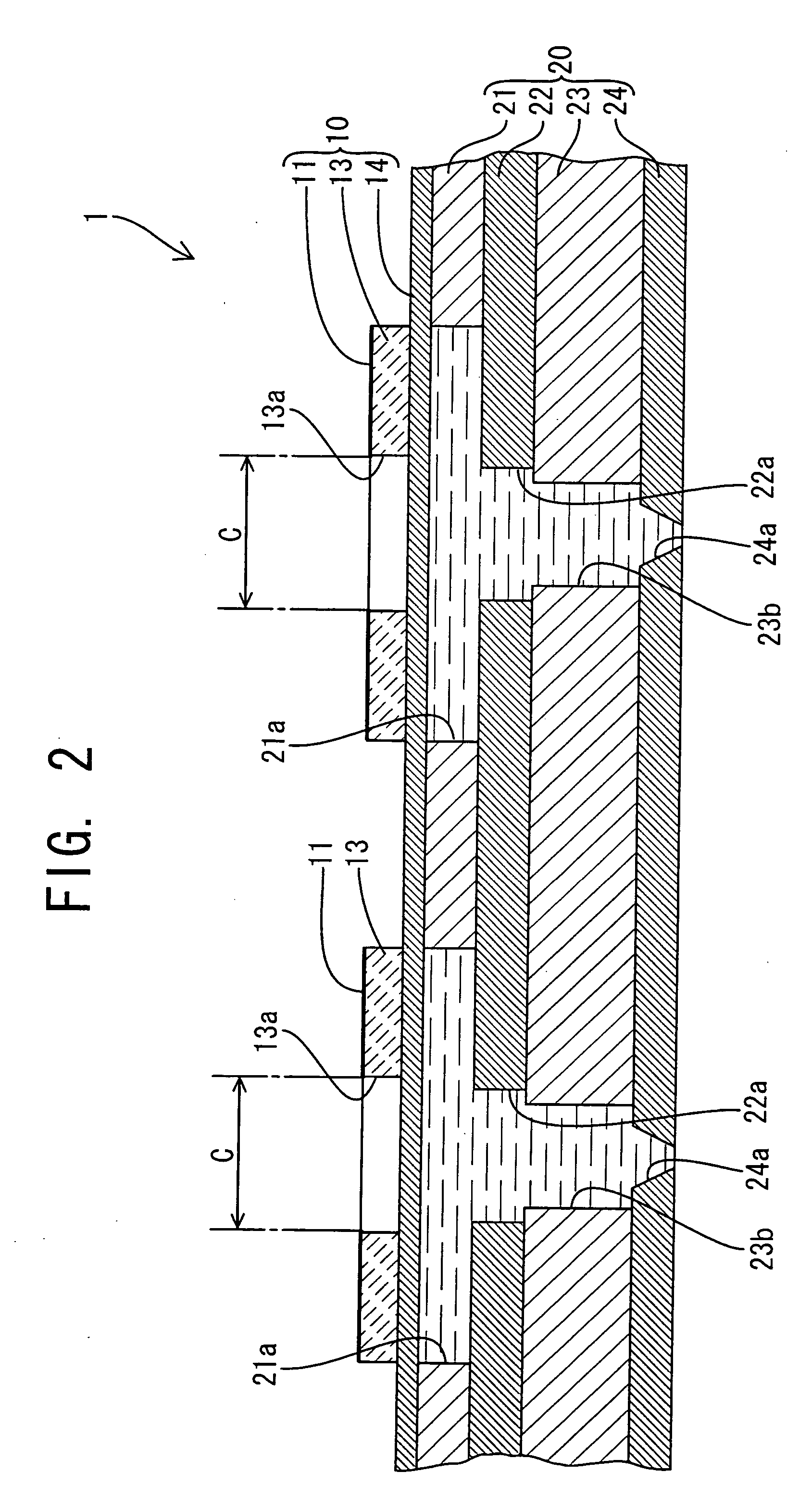
[0026] Referring to FIGS. 1-4, there will be described a liquid delivery apparatus 1 according to a first embodiment of the invention. FIG. 1 shows a cross sectional view of one of a plurality of pressure chambers 21a of the liquid delivery apparatus 1, taken along a line extending in the longitudinal direction of the chamber, while FIG. 2 is a cross sectional view of the apparatus 1 taken along an array of the plurality of pressure chambers 21a. FIG. 3 is a plan view of the apparatus 1 shown in FIGS. 1 and 2, while FIG. 4 is an explanatory view illustrating a state where the apparatus 1 is activated.

[0027] As shown in FIGS. 1 and 2, the liquid delivery apparatus 1 of the present embodiment takes, for example, the form of an ink jet head for emitting a jet of an ink, as a kind of liquid ejecting apparatus capable of emitting a jet of a liquid. The liquid delivery apparatus comprises a cavity plate 20 including a plurality of pressure chambers 21a in each of w...

second embodiment

[0043] Second Embodiment

[0044] There will be described a second embodiment of the invention by reference to FIG. 5.

[0045] The second embodiment is mostly identical with the first embodiment with some exceptions, which will be described. The identical elements will be denoted by the reference numerals used in the first embodiment, and illustration thereof is omitted.

[0046] A liquid delivery apparatus 1 according to the second embodiment comprises a diaphragm 14 formed of an electrically non-conductive material, piezoelectric layers 13, and a lower electrode 12 interposed between the piezoelectric layers 13 and the diaphragm 14, as shown in FIG. 5. The lower electrode 12 operates to apply an electric field to each of the piezoelectric layers 13 at least a part of the piezoelectric layer 13 positionally corresponding to an inner peripheral part of a corresponding one of pressure chambers 21a. According to this arrangement, even where the diaphragm 14 is formed of an electrically non-...

third embodiment

[0047] Third Embodiment

[0048] By reference to FIG. 6, there will be described a third embodiment of the invention.

[0049] The third embodiment is almost identical with the first embodiment with some exceptions, which will be described. The identical elements will be denoted by the reference numerals used in the first embodiment and illustration thereof is omitted.

[0050] In each of the first and second embodiments, the piezoelectric layer 13 is configured such that a void 13a is formed through the entire thickness of each piezoelectric layer 13 at the inner area C. However, piezoelectric layers 13 of the liquid delivery apparatus 1 according to the third embodiment are configured such that a halfway-through void is provided in each piezoelectric layer 13 at the inner area C. That is, as shown in FIG. 6, a part 13b of each piezoelectric layer 13 corresponding to the inner area C is made thinner than the other part or an annular thicker part of the piezoelectric layer 13 located over ...


PUM


Abstract

A liquid delivery apparatus comprises a pressure chamber accommodating a liquid, and a piezoelectric actuator plate which is disposed to close the pressure chamber and is deformed to deliver the liquid through an opening in communication with the pressure chamber. The actuator plate has a laminated structure including a piezoelectric layer which is deformable at least in a planar direction thereof by an application of an electric field to the piezoelectric layer, and a planar diaphragm laminated on the piezoelectric layer. A rigidity of the piezoelectric actuator plate is lower at a portion thereof over an inner side of an inner peripheral part of the pressure chamber than at a portion thereof over the inner peripheral part of the pressure chamber.

Description

[0001] The present application is based on Japanese Patent Application No. 2003-338382 filed on Sep. 29, 2003, the content of which is incorporated herein by reference. BACKGROUND OF THE INVENTION [0002] 1. Field of the Invention [0003] The present invention relates to a liquid delivery apparatus, and particularly to a liquid delivery apparatus actuated by a piezoelectric element. [0004] 2. Discussion of Related Art [0005] For instance, there is conventionally known an ejecting apparatus where a plurality of pressure chambers each accommodating a liquid is closed by a diaphragm which is deflected by a piezoelectric element so as to eject a droplet of the liquid from a nozzle. In such an apparatus, since the pressure applied to the liquid accommodated in the pressure chamber is increased with an increase in the amount of deflection of the diaphragm, the diaphragm is desired to be easily deformable or displaceable. [0006] A technique to increase the deflection of the diaphragm is disc...

Claims


Application Information

Patent Timeline
IPC IPC(8): B41J2/14F04B43/02F04B43/04
CPCB41J2/14233F04B43/046
Inventor SUGAHARA, HIROTO
Owner BROTHER KOGYO KK
Why Eureka
Try Eureka