Window sleeve for mounting framed windows

a window and window frame technology, applied in the field of window sleeves, can solve the problems of water damage to the building walls, affecting the thermal efficiency of the building, and requiring a level of skill for windows to be installed,

Inactive Publication Date: 2005-04-07
INELLI JOHN D
View PDF9 Cites 21 Cited by
  • Summary
  • Abstract
  • Description
  • Claims
  • Application Information

AI Technical Summary

Benefits of technology

[0004] In view of the aforementioned considerations, the present invention is directed to a window sleeve arrangement for positioning a window unit in an opening through an enclosure wall having an exterior surface and an interior surface, wherein the enclosure wall separates an interior space defined by the enclosure from an exterior space, the window unit having a frame surrounding at least one glass pane. The window sleeve comprises top and bottom walls joined by side walls. The walls each have an inner surface and an outer surface with an inner edge for positioning adjacent to the interior surface of the building wall and an outer edge for positioning adjacent to the exterior surface of the building wall. A first exterior flange is disposed around the walls of the sleeve and extends laterally inward from the outer surfaces of the walls at a location intermediate the inner and outer

Problems solved by technology

Quickly and conveniently mounting framed windows within a wall of an enclosure, such as the exterior wall of a building, is a task which needs improvement because installing windows is a labor intensive undertaking which involves considerable expense.
Moreover, installing windows requires a level of skill that many installers lack, so that windows are im

Method used


Image

  • Window sleeve for mounting framed windows
  • Window sleeve for mounting framed windows
  • Window sleeve for mounting framed windows

Examples


first embodiment

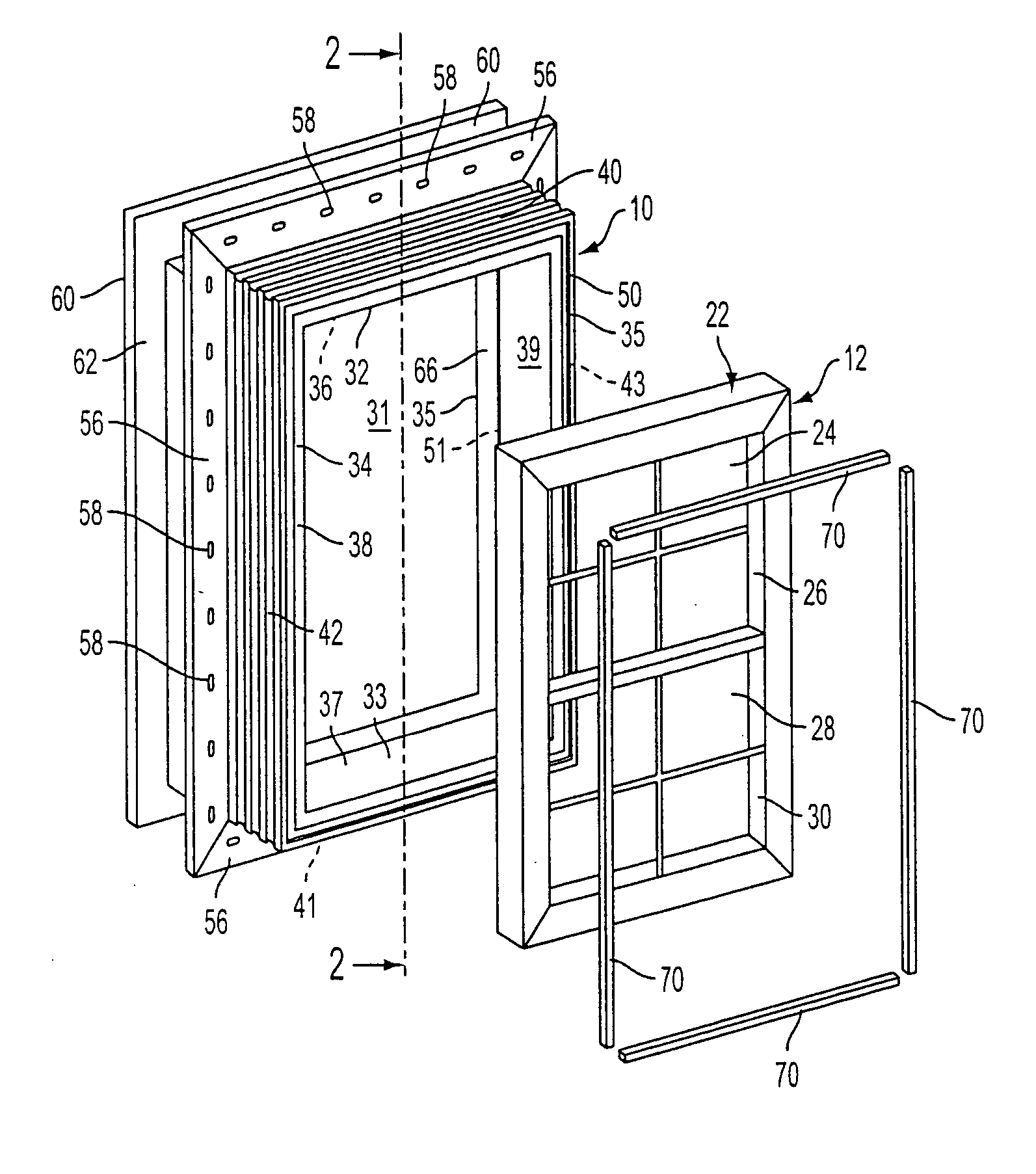
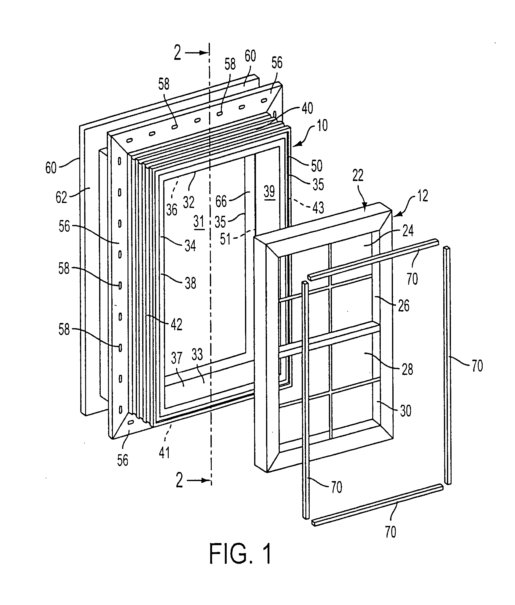
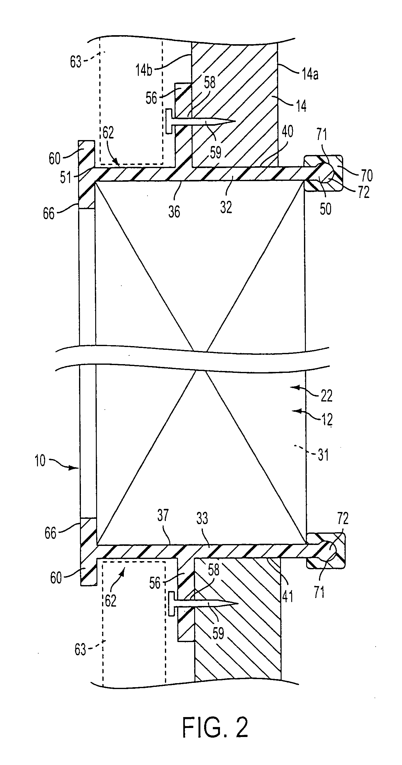
[0021] Referring mainly to FIG. 1, the window unit 12 includes a window frame 22 in which is mounted at least one window pane. In a first embodiment, the window frame 22 has window panes 24 and 28 mounted therein with the window pane 24 mounted in the sash 26 and the window pane 28 mounted in a sash 30. The rectangular window frame 22 is received within a rectangular enclosure 31 of the window sleeve 10 defined by an upper wall 32 which is joined to a lower wall 33 by first and second side walls 34 and 35. The walls 32, 33, 34 and 35 have inner wall surfaces 36, 37, 38 and 39, respectively, and outer wall surfaces 40, 41, 42 and 43, respectively. The walls 32, 33, 34 and 35 define an inside edge 50 and an outside edge 51, the inside edge 50 being adjacent the interior wall surface 14a and the outside edge 51 being adjacent the outside surface 14b of the enclosure wall 14.

[0022] In order to secure the window sleeve arrangement 10 in the opening 13 (FIG. 2) through the enclosure wall ...

embodiment 100

[0029] Referring now to FIGS. 6 and 7 where a preferred embodiment 100 of the window sleeve is illustrated, it is seen that the window sleeve 100 has a relatively thick cross-section so as to accommodate a relatively deep groove 102, which receives a resilient latching member 104 projecting from molding 106. The resilient latching member 104 forms a snap-in coupling comprising two spring-arm strips 108, each having a shoulder 110 that snaps behind shoulders 112 at the entrance to the slot 102.

[0030] Optionally, a decorative interior molding 120 has a resilient latching rib 122 that snaps into and latches with a second groove 124 in the window sleeve 100. The resilient rib member 122 has a structure similar to the resilient latching rib member 104. The decorative interior molding 120 overlies the interior surface 14b of the wall 14.

[0031]FIG. 8 is an elevational view of a variation of the preferred embodiment of the invention wherein decorative interior molding 120′ is attached to t...


PUM

PropertyMeasurementUnit
Angleaaaaaaaaaa
Sizeaaaaaaaaaa
Moldableaaaaaaaaaa

Abstract

A window sleeve arrangement for positioning a window unit in an opening through an enclosure wall has an interior surface for receiving the window unit and an outside surface for sliding into the opening through the enclosure wall. A first exterior flange engages the exterior surface of the enclosure wall, while a second exterior flange, spaced from the first exterior flange provides a gap for receiving sheathing on the outside of the building. Disposed within the window sleeve arrangement is an interior inwardly projecting flange which serves as a window stop to position the window adjacent the exterior wall of the building enclosure. The window unit is held within the window sleeve by a snap-in-place molding which engages the window unit. Optionally, interior decorative molding is coupled to the sleeve to cover a portion of the interior wall adjacent to the window sleeve. Preferably, the window sleeve assembly is made of plastic material, such as polyvinylchloride, polyurethane, polypropylene, ABS composite, ABS cellular plastics, plastic composites, cellular plastics or any other type of suitable plastic material.

Description

FIELD OF THE INVENTION [0001] The present invention is related to devices for mounting framed windows. More particularly, the present invention is related to devices for mounting framed windows through openings in walls, wherein the devices are configured as window sleeve arrangements surrounding framed windows. BACKGROUND OF THE INVENTION [0002] Quickly and conveniently mounting framed windows within a wall of an enclosure, such as the exterior wall of a building, is a task which needs improvement because installing windows is a labor intensive undertaking which involves considerable expense. Moreover, installing windows requires a level of skill that many installers lack, so that windows are improperly installed resulting in leaks wherein, not only water, but air passes between the window frame and opening though the wall in which the window is mounted. Leaks not only compromise the thermal efficiency of buildings, but also can result in water damage within buildings and to buildi...

Claims


Application Information

Patent Timeline
IPC IPC(8): E06B1/02E06B1/30
CPCE06B1/30E06B1/02
Inventor INELLI, JOHN D.
Owner INELLI JOHN D
Why Eureka
Try Eureka