
Tire pressure indicator

a technology of tire pressure and indicator, which is applied in the direction of vehicle tyre testing, instruments, roads, etc., can solve the problems of shortened life expectancy of tires, dangerous impairment of road traction and steering control, and reduced overall vehicle fuel and mechanical efficiency, so as to prevent corrosion or deterioration

Inactive Publication Date: 2005-04-07
PERLIN MIKE +1
View PDF9 Cites 18 Cited by
  • Summary
  • Abstract
  • Description
  • Claims
  • Application Information

AI Technical Summary

Benefits of technology

[0008] The present invention involves several different embodiments related to a tire pressure indicator for monitoring and indicating pressure inside vehicle tires that provides accurate results and is able to operate for extended periods of time under the extreme operating conditions of tires.
[0013] The indicator may also include a filter that permits air therethrough, but prevents moisture from passing therethrough. Accordingly, the indicator is able to maintain appropriate relation with atmospheric pressure while preventing corrosion or deterioration caused by moisture.

Problems solved by technology

If such a tire is operated at air pressures below its recommended design pressure, the likely effects include substantially shortened life expectancy of the tires, dangerous impairment to road traction and steering control required for safe vehicle operation, and reduced overall vehicle fuel and mechanical efficiency.
The proper maintenance of tire pressure has and continues to be an unsolved problem for the vast majority of vehicle owners and operators.
Manually checking the pressure of each tire on a regular basis is both a nuisance and inconvenience to the average vehicle operator.
Typically, the majority of vehicle tires go unchecked and result in abnormal tire wear that is identified by visual observation or when the vehicle handling becomes noticeably impaired.
However, most of these devices are either not accurate or are not able to withstand the environmental conditions (temperature extremes, extreme pressure excursions, moisture, contaminates, or striking, such as by rocks or other debris) to which tires are subject.

Method used


Image

  • Tire pressure indicator
  • Tire pressure indicator
  • Tire pressure indicator

Examples


Embodiment Construction

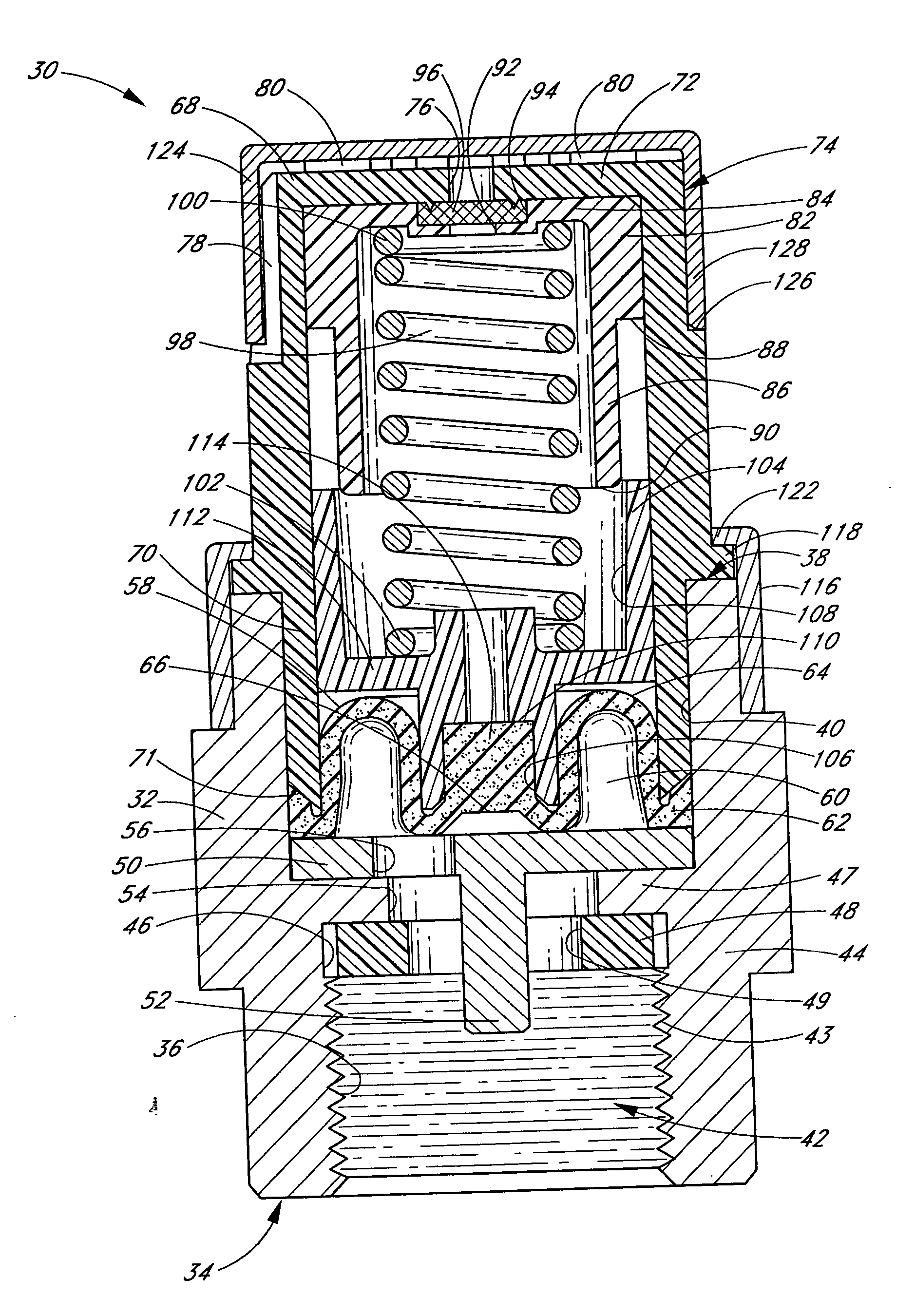
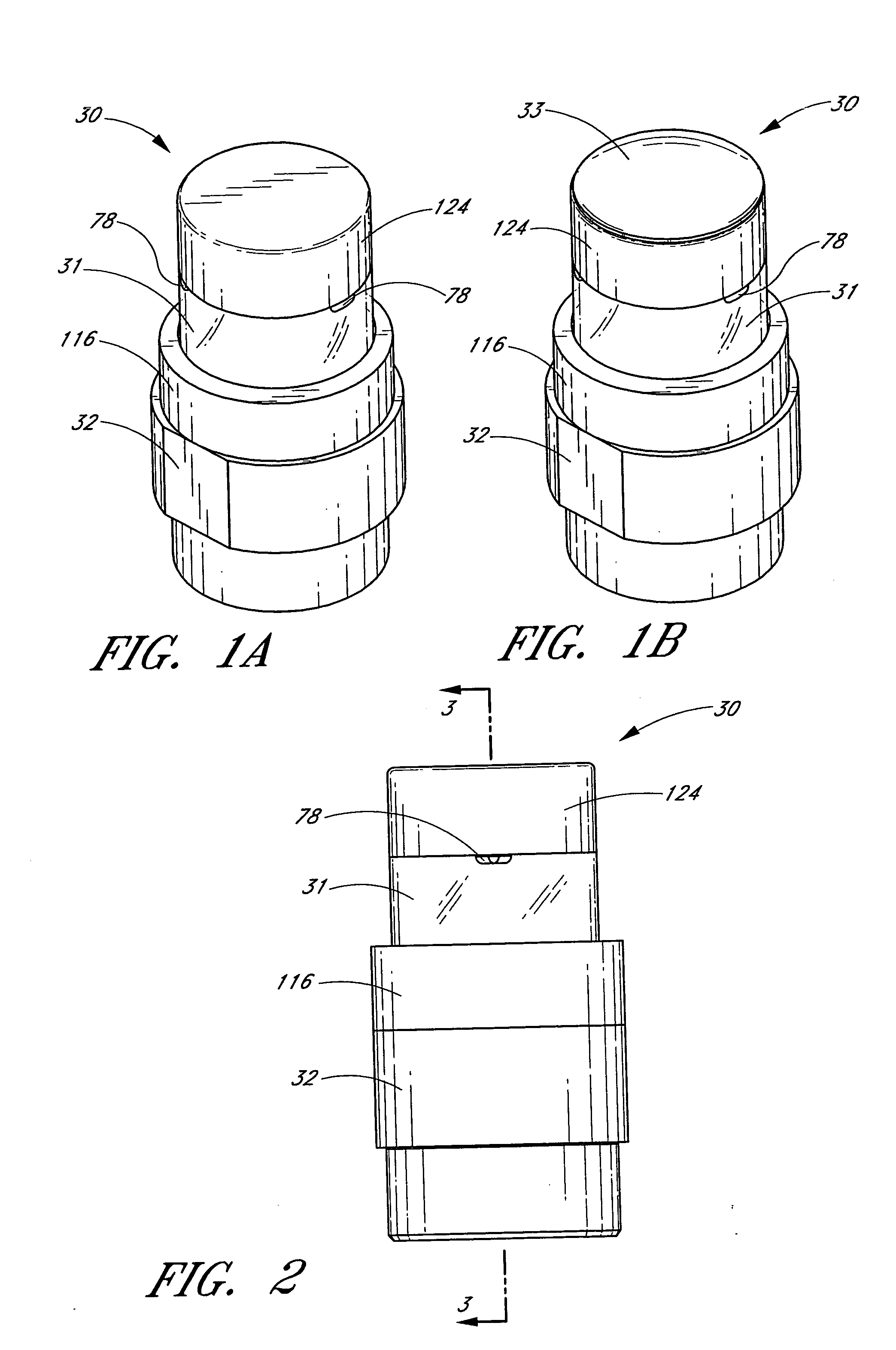
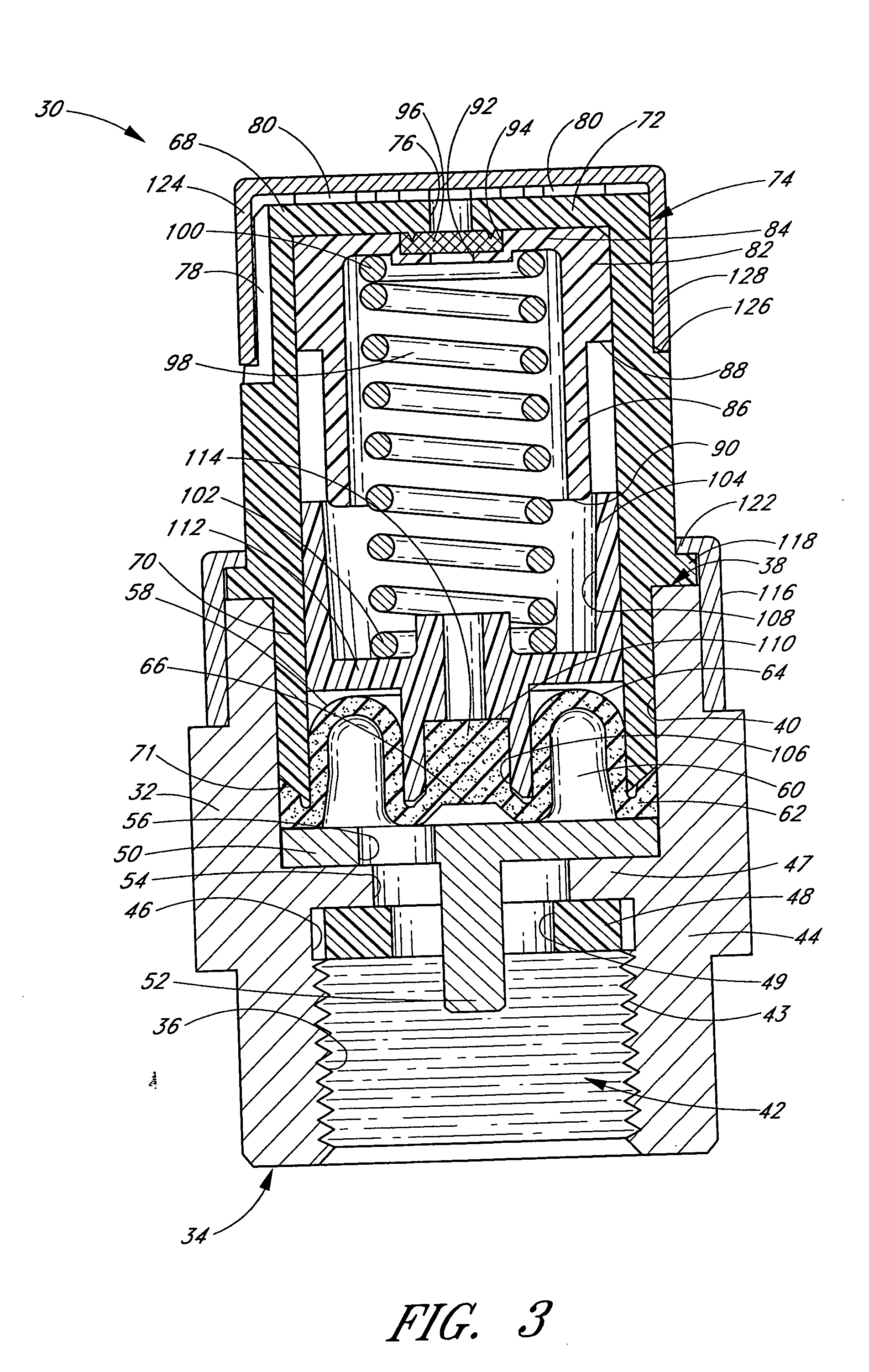
[0027]FIGS. 1A, 1B, and 2 illustrate embodiments of a tire pressure indicator 30 for monitoring and indicating pressure inside vehicle tires. The tire pressure indicator 30 may indicate pressure by displaying a color visible through a pressure indicator window. The tire pressure indicator 30 may also be adjusted so as to monitor and indicate correct pressure within a wide variety of different types of tires. For example, the tire pressure indicator 30 may be used on the tires of motorbikes, automobiles, trucks, specialized vehicles such as airplanes, cranes, construction vehicles, as well as military vehicles. In one embodiment, the tire pressure indicator 30 is adjustable for pressures ranging between 20 psi and 45 psi. In another embodiment, the tire pressure indicator 30 is adjustable for pressures ranging between about 14 psi and about 126 psi. In other embodiments, the tire pressure indicator 30 may be adjustable for pressure ranges substantially less than about 14 psi or subst...


PUM


Abstract

Disclosed herein are embodiments of a tire pressure indicator (30) for providing indication of a tire's pressure. The indicator (30) may include first and second indicators (82, 104) corresponding to first and second ranges of tire pressures. The indicator (30) may also include a rolling diaphragm (58) that actuates display of the first or second indicators (82, 104). The indicator (30) may include a plurality of channels (78) that permit communication of air between an exterior portion of the indicator (30) and an interior portion of the indicator (30) and a filter (96) that permits air therethrough, but prevents moisture from passing therethrough.

Description

RELATED APPLICATIONS [0001] This application claims priority of U.S. application Ser. No. 60 / 493,507, filed Aug. 8, 2003, entitled TIRE PRESSURE GAUGE, and is a continuation-in-part of U.S. application Ser. No. 29 / 191,803, filed Oct. 13, 2003, entitled PRESSURE GAUGE, both of which are incorporated herein in their entirety.BACKGROUND OF THE INVENTION [0002] 1. Field of the Invention [0003] This invention relates generally to pressure indicators and, more particularly, to a tire pressure indicator for monitoring and indicating pressure inside vehicle tires. [0004] 2. Description of the Related Art [0005] Maintaining the proper air pressure in pneumatic vehicle tires is critical for the safe and efficient operation of the tire as well as the vehicle as a whole. If such a tire is operated at air pressures below its recommended design pressure, the likely effects include substantially shortened life expectancy of the tires, dangerous impairment to road traction and steering control requ...

Claims


Application Information

Patent Timeline
IPC IPC(8): B60CB60C23/00B60C23/04
CPCB60C23/0496B60C23/0408
Inventor PERLIN, MIKEMURI, JOHN I.
Owner PERLIN MIKE
Learn More