Shell and tube heat exchanger

a heat exchanger and shell technology, applied in the field of heat exchangers, can solve the problems of heat exchangers experiencing severe external wall thinning of tubes beyond allowable limits, corrosion, and persistent problems, and achieve the effect of preventing fouling and corrosion

Inactive Publication Date: 2009-01-01
KING FAHD UNIVERSITY OF PETROLEUM AND MINERALS
View PDF34 Cites 23 Cited by
  • Summary
  • Abstract
  • Description
  • Claims
  • Application Information

AI Technical Summary

Benefits of technology

[0009]The shell and tube heat exchanger includes a shell having a fluid inlet and a fluid outlet, and a plurality of tubes disposed inside the shell, the tubes having a fluid inlet and a fluid outlet. An impingement baffle having a plurality of perforations is disposed in the shell between the shell fluid inlet and the tubes. The impingement baffle is configured to guide a heat exchanger fluid from the shell fluid inlet to distribute the heat exchanger fluid uniformly around the tubes. The perforations prevent recirculation and stagnation of fluid flow behind the baffle, thereby preventing fouling and corrosion with subsequent thinning of the tube walls.

Problems solved by technology

This method is effective enough in distributing the shell side fluid more or less uniformly around the tube bundles, but seems to be accompanied by fouling and corrosion on the tubes in the region next to inlet baffle plate.
Due to fouling and corrosion, these heat exchangers experience severe external wall thinning of the tubes beyond allowable limits.
Several attempts have been made to eliminate the problem by upgrading the tube metallurgy, but the problem has persisted.
Moreover, the recirculation zones encourage impurities and particles carried by the fluid to foul, (deposit), and create active corrosion that causes a thinning process in the tube wall to the extent that the heat exchanger must be replaced when the walls are too thin for safe operations.

Method used


Image

  • Shell and tube heat exchanger
  • Shell and tube heat exchanger
  • Shell and tube heat exchanger

Examples


Embodiment Construction

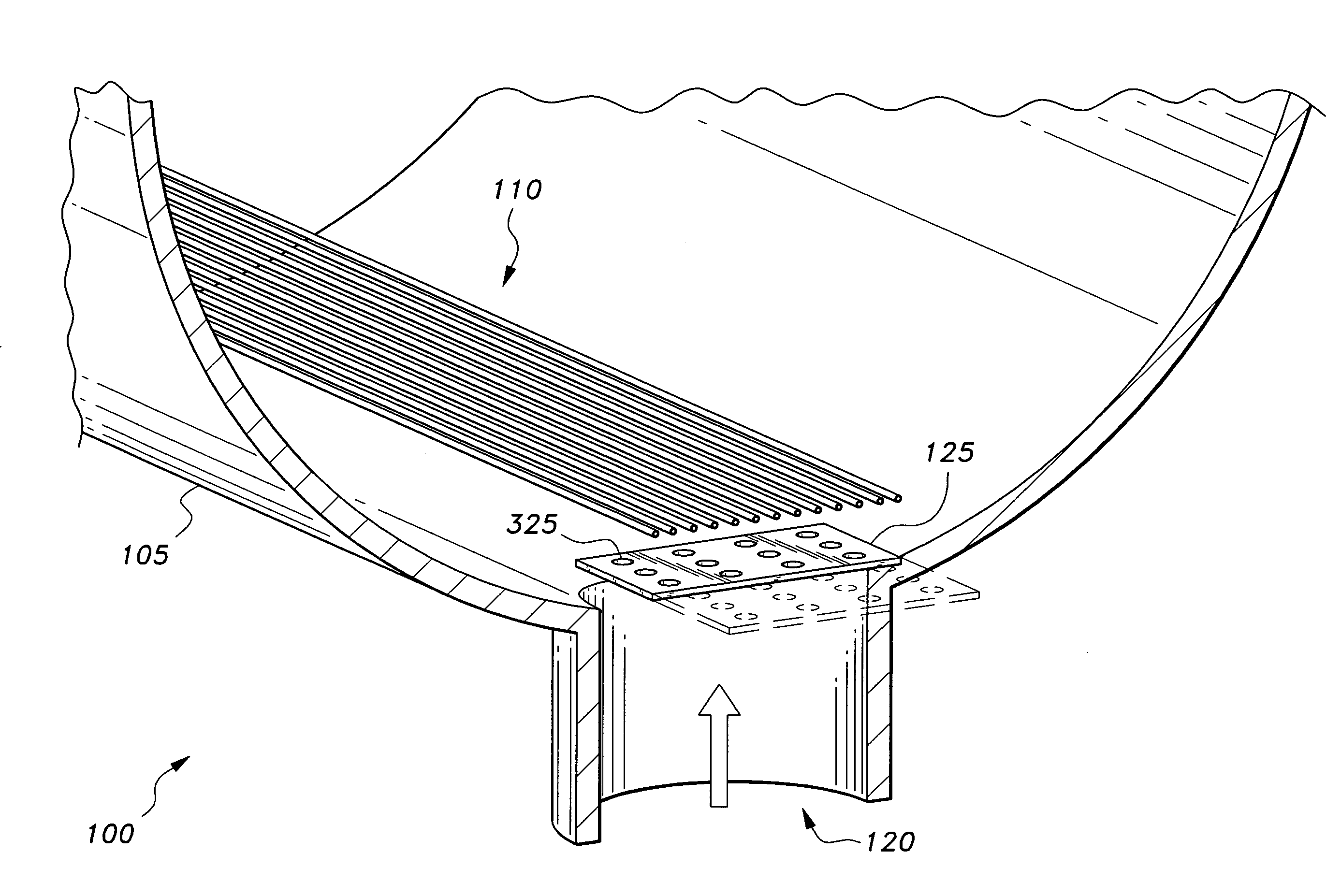
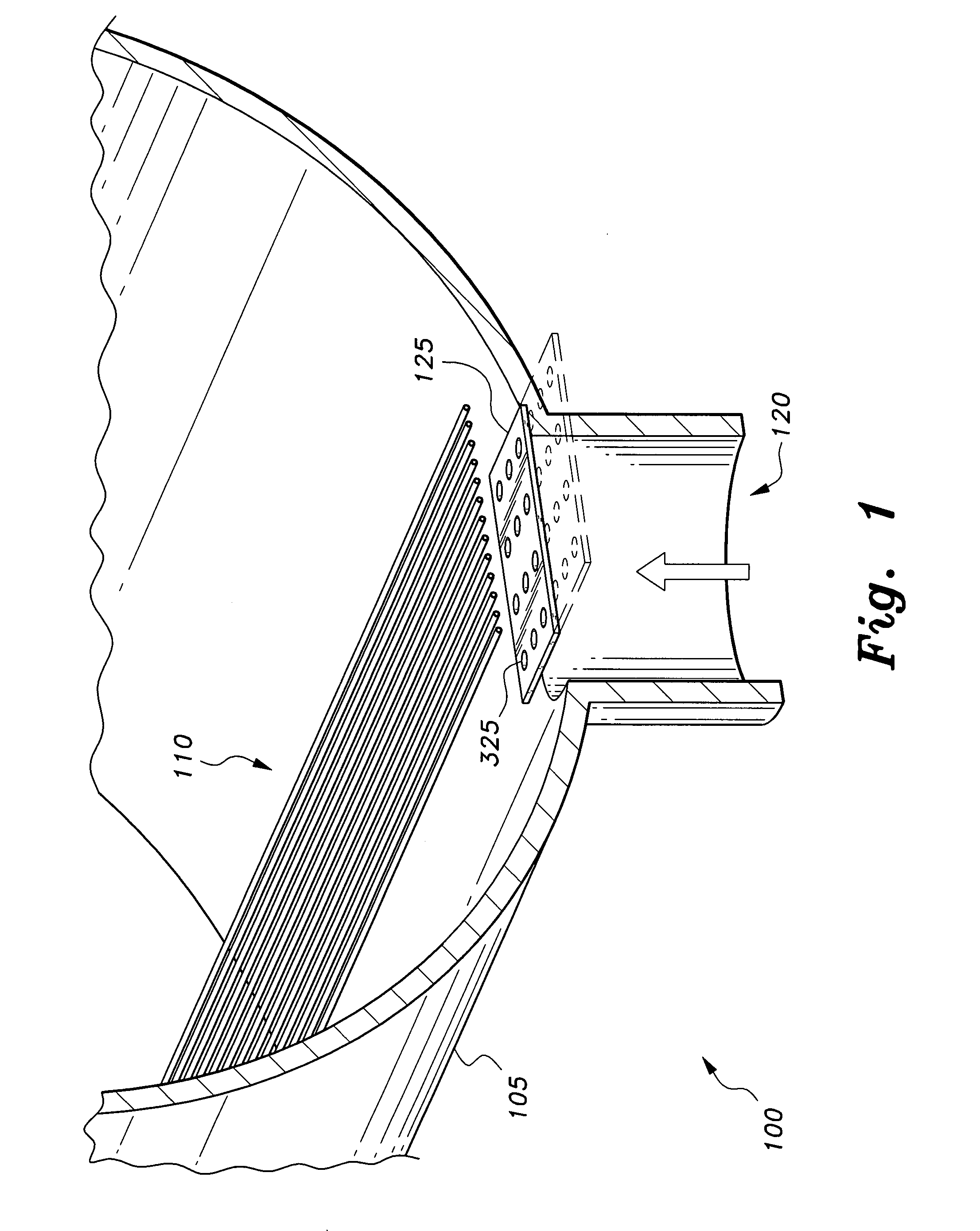
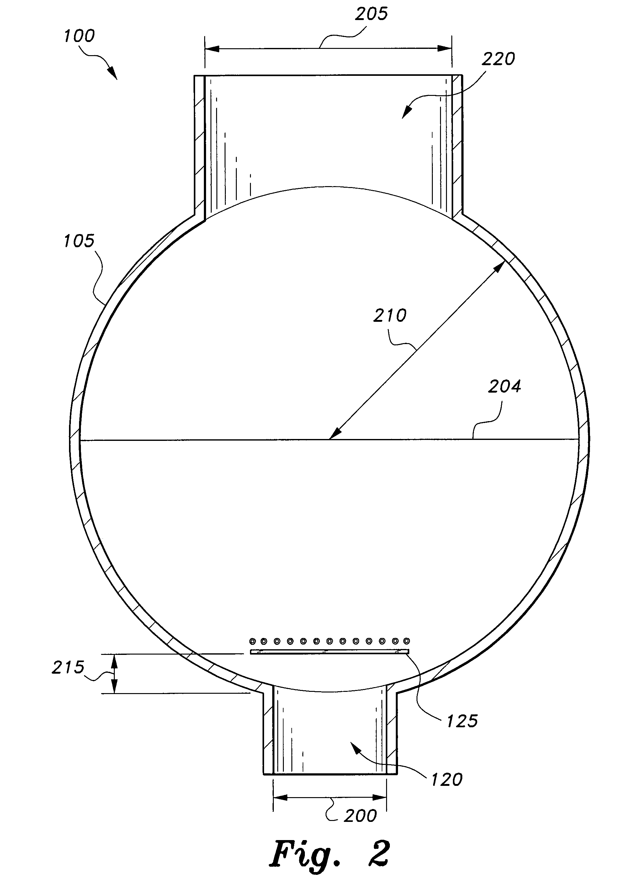
[0018]As shown in FIGS. 1 and 2, the present invention is a shell and tube heat exchanger 100 that includes a shell housing 105 having at least one shell inlet port 120 for flow of a heat exchanger fluid through the shell 105. An exemplary inlet port 120 can have a diameter 200 of approximately 200 mm. At least one impingement baffle plate 125 having a plurality of perforations 325 defined therein is disposed in the shell 105 proximate to the shell inlet port 120 normal to the direction of fluid flow through the inlet, e.g., a distance 215 of approximately 117 mm from the mouth of the inlet 120. As shown in FIG. 3, the perforations 325 are disposed on a symmetric half of the baffle 125, e.g., with transverse pitch (Tp) as shown being approximately 50 mm, longitudinal pitch (Lp) as shown being approximately 32.5 mm, each perforation having a diameter 305 of approximately 25 mm. It will be understood that the baffle plate dimensions may be scaled up or down, depending on the heat exch...


PUM


Abstract

The shell and tube heat exchanger includes a shell having a fluid inlet and a fluid outlet, and a plurality of tubes disposed inside the shell, the tubes having a fluid inlet and a fluid outlet. An impingement baffle having a plurality of perforations is disposed in the shell between the shell fluid inlet and the tubes. The impingement baffle is configured to guide a heat exchanger fluid from the shell fluid inlet to distribute the heat exchanger fluid uniformly around the tubes. The perforations prevent recirculation and stagnation of fluid flow behind the baffle, thereby preventing fouling and corrosion with subsequent thinning of the tube walls.

Description

BACKGROUND OF THE INVENTION[0001]1. Field of the Invention[0002]The present invention relates to a heat exchanger, and more particularly to a shell and tube heat exchanger having improved resistance to fouling of the exchanger fluid and corrosion of the tubes.[0003]2. Description of the Related Art[0004]A shell and tube heat exchanger is a class of heat exchanger that is most commonly found in oil refineries and other large chemical processing plants. This type of heat exchanger comprises a shell, i.e., a large vessel, and a bundle of tubes inside the shell. The shell and tube heat exchanger is designed to allow two fluids of different starting temperatures to flow through it. A first fluid flows through the tubes (the tube side), while a second fluid flows in the shell (the shell side) but outside the tubes. Heat is transferred between the two fluids through the tube walls, either from tube side to shell side or vice versa. The fluids may be either liquids or gases on either the sh...

Claims


Application Information

Patent Timeline
Patent Type & Authority Applications(United States)
IPC IPC(8): F28F19/00
CPCF28D7/16F28F19/00F28F9/0265
Inventor AL-HADHRAMI, LUAI M.
Owner KING FAHD UNIVERSITY OF PETROLEUM AND MINERALS
Why Eureka
Try Eureka