
Ergonomic clutch actuator

Inactive Publication Date: 2005-04-07
MAGNETI MARELLI POWERTRAIN USA
View PDF33 Cites 18 Cited by
  • Summary
  • Abstract
  • Description
  • Claims
  • Application Information

AI Technical Summary

Benefits of technology

An aspect of the present invention is to provide an ergonomic manual clutch actuator assembly for a straddle-type vehicle. The assembly includes a manual clutch lever pivotally mounted to a handlebar of the vehicle for actuating a clutch cable so that retraction of the clutch lever draws the clutch cable, and release of the clutch lever releases the clutch cable. A clutch actuator mechanism is provided within the housing of the vehicle proximate to a distal end of a clutch shaft extending from a clutch. The clutch actuator mechanism is driven by the clutch cable so that when the cable is drawn, the clutch actuator mechanism biases the clutch shaft and disengages the clutch, and when the cable is released, the clutch shaft returns to the engaged position. A first predefined force is required to pivot the clutch lever away from a normal extended position. A second predefined force, greater than the first force, is required to pivot the clutch lever to an intermediate position. A third predefined force is required to maintain the clutch lever in a retracted position and the third force is less than the second force to reduce operator fatigue.

Problems solved by technology

For example, in straddle-type vehicles that have a high torque output, a correspondingly high force of friction is required to maintain the engagement of a clutch.
The drawback to this option, however, is the user must maintain the clutch lever in the fully retracted position, which also corresponds with the maximum manual imparted force.
As time and repetitions increase, the hand of the operator experiences fatigue which may be undesirable.
This load increases friction between the swash plate and rollers, and between the rollers within the corresponding tapered tracks.
This friction reduces the efficiency of the clutch actuator and adds to the manually imparted force required to actuate the clutch.
However, the sheathing also generates friction as the clutch cable is drawn and released.

Method used


Image

  • Ergonomic clutch actuator
  • Ergonomic clutch actuator
  • Ergonomic clutch actuator

Examples


Embodiment Construction

)

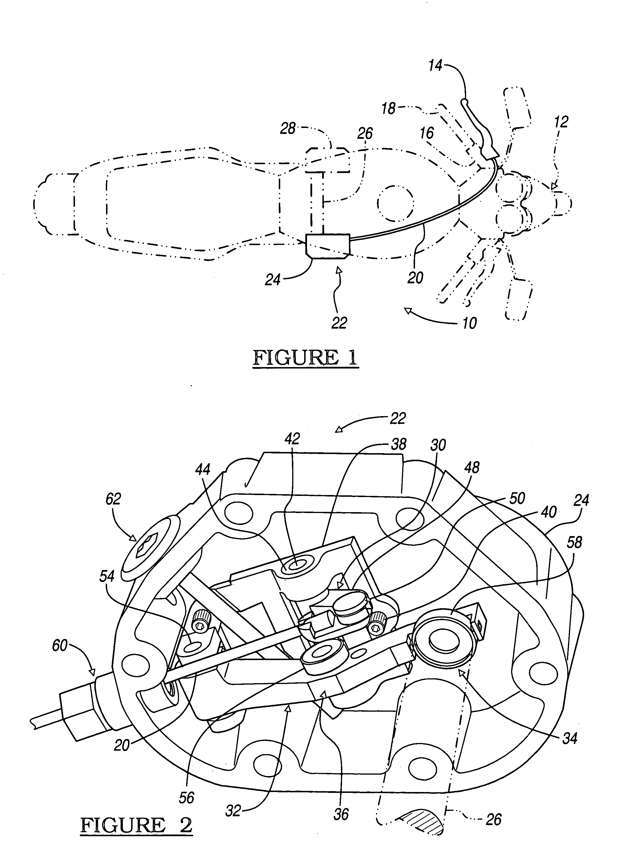
With reference now to FIG. 1, an ergonomic manual clutch actuator assembly is illustrated and indicated generally by reference numeral 10. The clutch actuator assembly 10 is illustrated in communication with a straddle-type vehicle, particularly a motorcycle 12 illustrated in phantom. The clutch actuator assembly 10 includes a manual clutch lever 14 pivotally mounted to a handlebar 16 of the motorcycle 12. The clutch lever 14 is oriented adjacent to a hand grip 18 at a distal end of the handlebar 16, such that a user may grip the handlebar 16 and concurrently operate the clutch actuator assembly by pivoting the clutch lever 14.

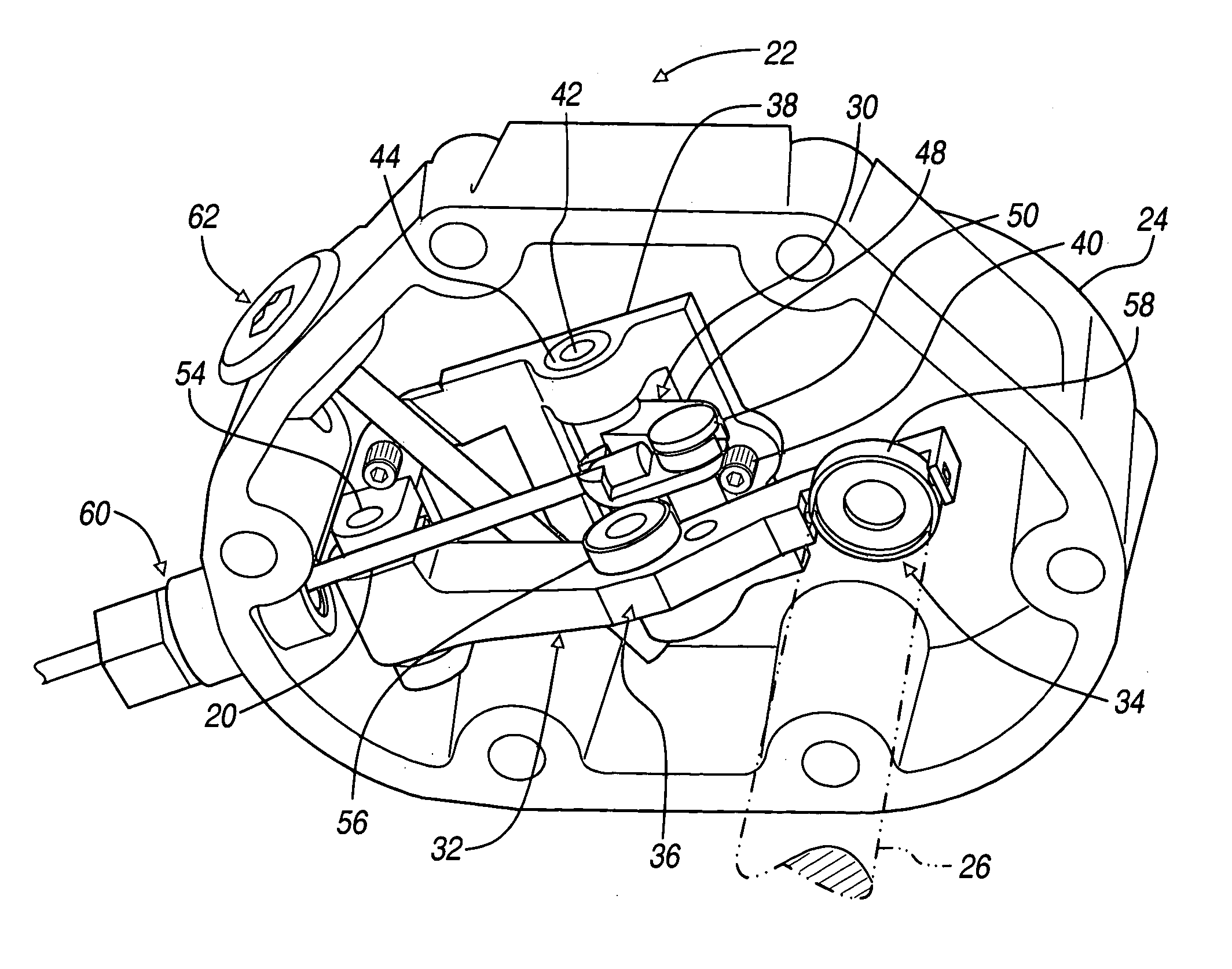
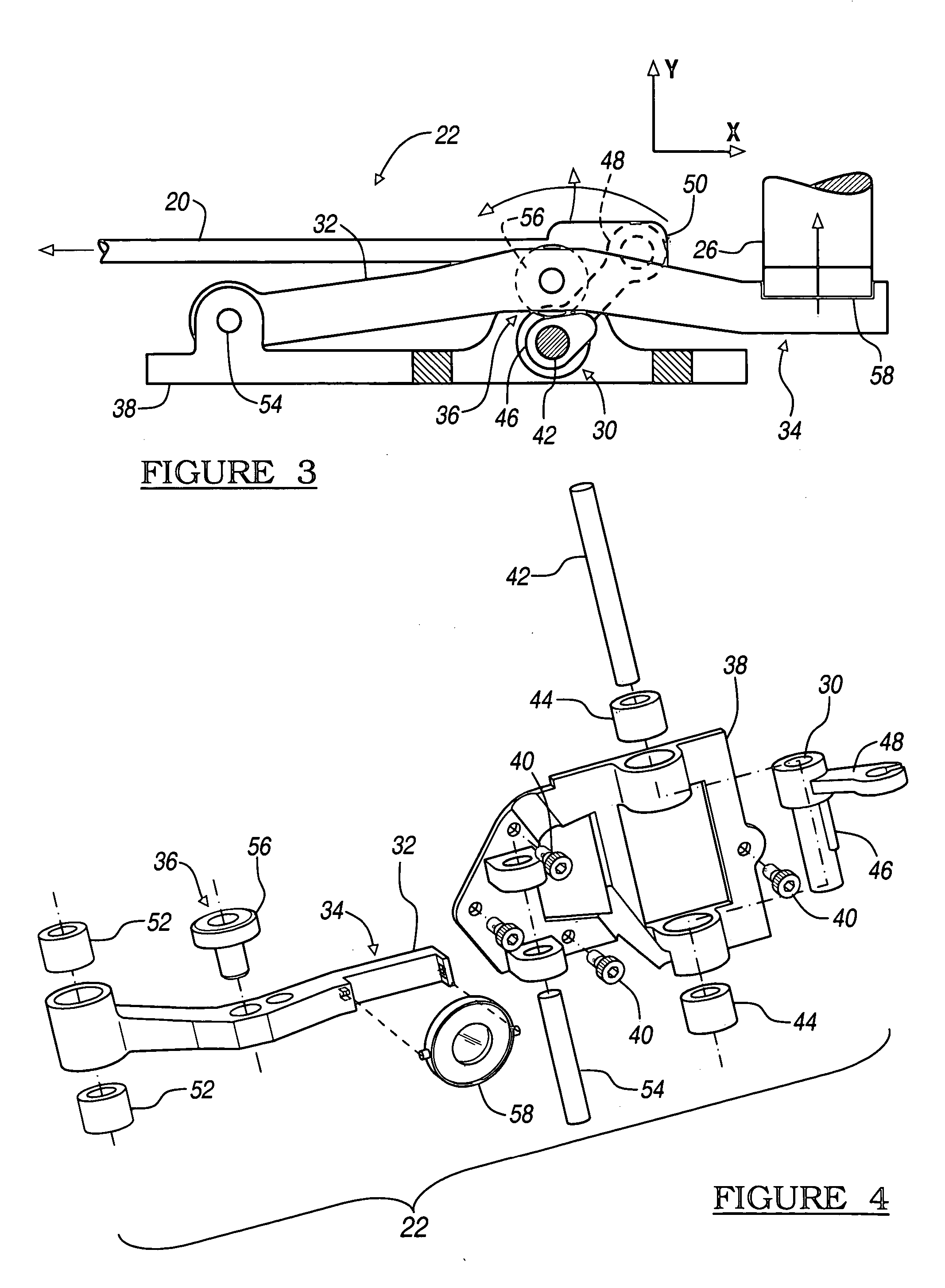
A clutch cable 20 is connected to the clutch lever 14 so that retraction of the clutch lever 14 draws the clutch cable 20 and release of the clutch lever 14 releases the clutch cable 20. A clutch actuator mechanism 22 is provided within a housing 24 of the motorcycle 12. The housing is illustrated as oriented on a lateral side of the motorcycle 12 so that ...


PUM


Abstract

The present invention discloses an ergonomic manual clutch actuator assembly, and a method for providing the manual clutch actuator assembly, for a straddle-type vehicle or the like. The assembly includes a manual clutch lever pivotally mounted to a handlebar for drawing a clutch cable connected to a clutch actuator mechanism. The clutch actuator mechanism is provided within the housing of the vehicle for cooperating with a distal end of a clutch shaft for disengaging a clutch when the cable is drawn. The clutch actuator assembly requires a first predefined force to pivot the clutch lever away from a normal extended position. A second predefined force, being greater than the first force, is required to further pivot the clutch lever to an intermediate position. Also, a third predefined force is required to maintain the clutch lever in a retracted position, the third force is less than the second force.

Description

BACKGROUND OF THE INVENTION 1. Field of the Invention The present invention relates generally to a clutch actuator, more particularly to an ergonomic manual clutch actuator assembly for a motorcycle for reducing operator fatigue. 2. Background Art Straddle-type vehicles, particularly motorcycles, include a motor for imparting power to a transmission for driving the vehicle. Typically, the motor is an internal combustion engine and the transmission has a plurality of gear reduction ratios for offering a variety of operable modes to a user. In order to shift between gear reduction ratios of the transmission, a clutch is typically utilized between the motor or engine and the transmission. The clutch may be actuated by an actuator that may receive a signal from the user or from an engine control unit, signaling to engage or disengage the clutch. Alternatively, and more commonly, the clutch is actuated by a manually imparted force through a manual clutch lever, which is pivotally mo...

Claims


Application Information

Patent Timeline
IPC IPC(8): B62K11/14F16D23/12
CPCB62K11/14Y10T74/2057F16D23/12
Inventor PEPPARD, MICHAEL B.FOWLER, JOHN
Owner MAGNETI MARELLI POWERTRAIN USA
Learn More