Axial gap type dynamo-electric machine

a dynamo-electric machine and axial gap technology, applied in the direction of magnetic circuit rotating parts, magnetic circuit shape/form/construction, transportation and packaging, etc., can solve the problems of significant increase in loss and temperature rise rate, and achieve the effect of reducing induced current, effective reduction of induced current, and increasing electric resistan

Inactive Publication Date: 2005-04-07
YAMAHA MOTOR CO LTD
View PDF7 Cites 41 Cited by
  • Summary
  • Abstract
  • Description
  • Claims
  • Application Information

AI Technical Summary

Benefits of technology

[0025] According to the constitution, the induced current can effectively be reduced. That is, normally, a press fit face of the laminated teeth which is press-fit to the fixing hole is brought into close contact and the current is liable to flow and therefore, the eddy current is made to flow between the laminated plate members for the teeth. According to the invention, an electric resistance is increased and the induced current is reduced by providing a space or an insulating member or the like at the press fit close contact face.

Problems solved by technology

Although the loss of energy by the heat does not cause a serious problem in the case of a low output, when a strong magnet is used for achieving a large torque as in, for example, an electric two-wheeled vehicle, the loss is significantly increased and also a temperature rise rate is increased to bring about high temperatures.

Method used


Image

  • Axial gap type dynamo-electric machine
  • Axial gap type dynamo-electric machine
  • Axial gap type dynamo-electric machine

Examples


Embodiment Construction

[0048] A description will be given of embodiments of the invention with reference to the drawings as follows.

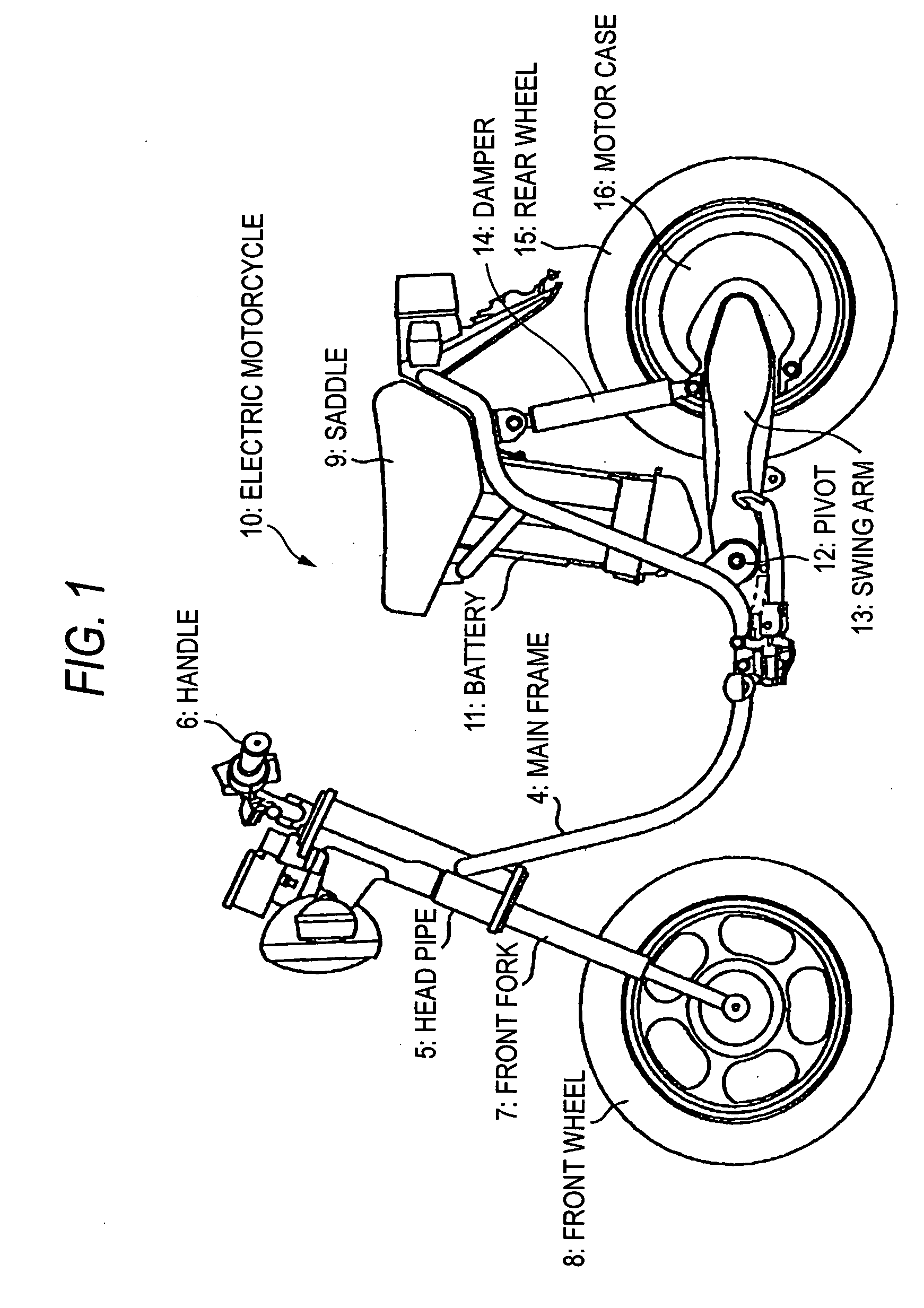
[0049]FIG. 1 is a side view of an electric two-wheeled vehicle to which an axial gap type electric motor of the invention is applied.

[0050] The electric two-wheeled vehicle 10 is mounted with a steering shaft (not illustrated) of a handle 6 which is inserted to a head pipe 5 fixedly attached to a front end of a main frame 4 and supports a front wheel 8 via a front fork 7 connected thereto. A saddle 9 is provided at a central portion of a vehicle body and a battery 11 is fixed to the main frame 4 on a lower side of the saddle. A swing arm 13 is pivotably supported by way of a pivot 12 via a damper 14 from a central portion to a rear side of the main frame 4. A motor case 16 is integrally formed at a rear end portion on the swing arm 13. An axial gap type electric motor according to the invention, mentioned later, is mounted to inside of the motor case 16 along with an axle (...


PUM


Abstract

There is provided an axial gap type rotating electric machine which is small-sized and achieves a high motor efficiency as a drive source having a high torque using, for example, a strong magnet by reducing an energy loss by an induced current.
An axial gap type rotating electric machine having a yoke on a side of a rotor in a circular plate shape fixed to a rotating shaft, a yoke 23 on a side of a stator in a circular plate shape opposed to the yoke on the side of the rotor, a magnet fixed to a side of an opposed face of either one of the yokes on the side of the rotor or the side of the stator, a plurality of teeth 24 arranged on a side of an opposed face of other yoke on the side of the rotor or the side of the stator radially and opposedly to the magnet and fixed to the yoke 23, and a coil wound around each of the plurality of teeth, in which the teeth 24 has a laminated member of plate members 124 for the teeth and faces 124a to be superposed of the plate members 124 for the teeth are arranged in a circumferential direction.

Description

TECHNICAL FIELD [0001] The present invention relates to a rotating electric machine having a rotor and a stator constituting an electric motor, a generator or the like and utilizing both operation of a motor and a generator as a regenerative brake when the rotating electric machine is used as a drive source of a vehicle. BACKGROUND ART [0002] A radial gap type electric motor is used as a general electric motor of a drive source or the like of an electric two-wheeled vehicle or the like. The radial gap type electric motor is provided with a magnet around an axis in a cylindrical shape on a side of, for example, a rotor, and provided with a plurality of teeth opposed to a cylindrical face of the magnet on a side of a stator and wound with coils around the teeth. Therefore, a gap between opposed faces of the magnet and the respective teeth is formed in a cylindrical shape along the axis. [0003] Meanwhile, an axial gap type electric motor is used as a rotation drive source of an audio a...

Claims


Application Information

Patent Timeline
Patent Type & Authority Applications(United States)
IPC IPC(8): H02K1/14
CPCB60G2204/30H02K2201/15H02K1/148H02K1/18
Inventor NAITO, SHINYAHINO, HARUYOSHI
Owner YAMAHA MOTOR CO LTD
Why Eureka
Try Eureka