
Air tunnel diverter and method of installing same

Active Publication Date: 2005-04-14
MAYTAG
View PDF9 Cites 9 Cited by
  • Summary
  • Abstract
  • Description
  • Claims
  • Application Information

AI Technical Summary

Benefits of technology

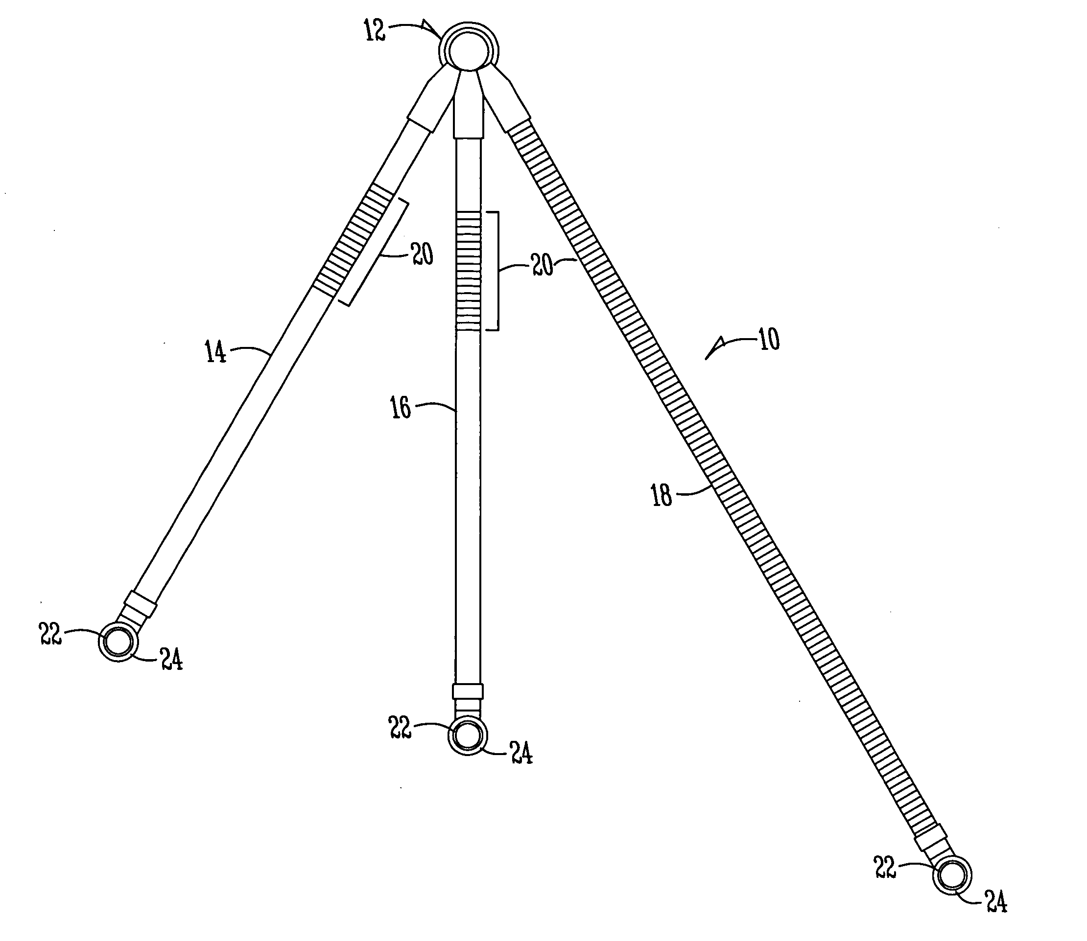
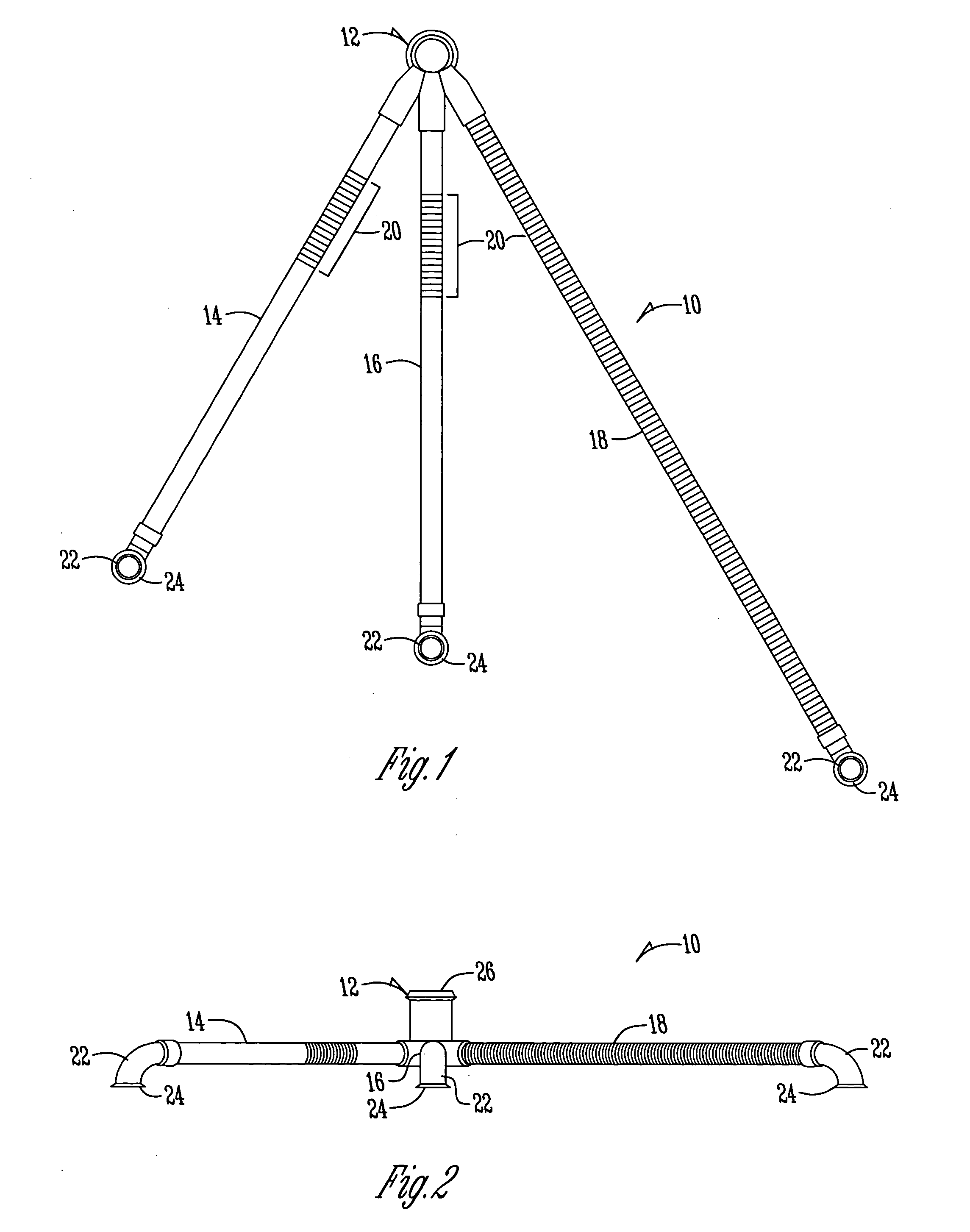
[0012] The present invention generally comprises a refrigeration unit including an air tunnel diverter and the method for installing the same. More specifically, the present invention generally includes an air tunnel diverter having a hub with one or more air tubes extending therefrom. The air tubes are secured to the hub and sealed with an overmold of a soft plastic flexible material. The air tubes are then inserted into the mullion area of the refrigeration unit or as needed to direct cooled air into refrigerated spaces. Each air tube preferably terminates in a fitting. The flexibility of the air tube allows the installer to easily position the fittings into the desired locations. Once properly positioned, the air tunnel diverter is secured in place by the surrounding insulation material in the mullion.

Problems solved by technology

Glue is messy and often ineffective, failing to properly seal the air tunnel diverters.
If the air tunnel diverters are not properly sealed, the foam insulation, which is typically sprayed on, may creep into the interior of the diverter, thereby reducing the diverters' effectiveness.

Method used


Image

  • Air tunnel diverter and method of installing same
  • Air tunnel diverter and method of installing same
  • Air tunnel diverter and method of installing same

Examples


Embodiment Construction

[0018] The present invention will be described as it applies to its preferred embodiment. It is not intended that the present invention be limited to the preferred embodiment. It is intended that the invention cover all modifications and alternatives that may be included within the spirit and scope of the invention.

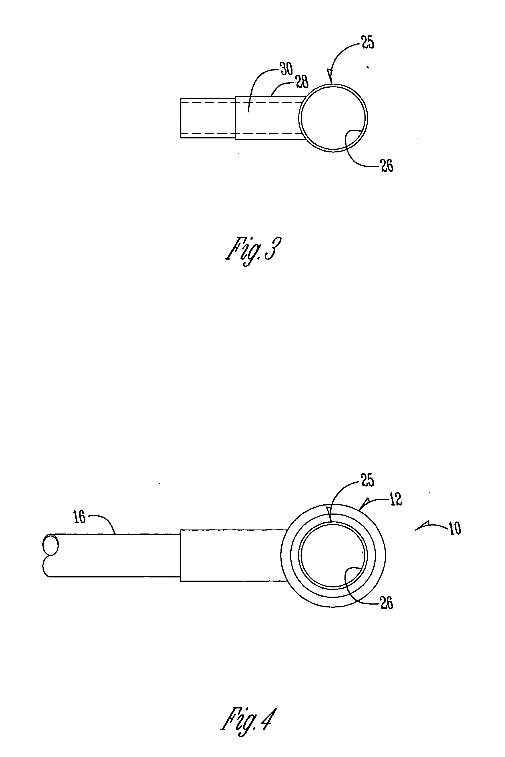
[0019] The present invention relates to fluid distribution devices generally referred to as air tunnel diverters and, in particular, to their configuration and fabrication. FIGS. 1-5 depict an exemplary diverter 10 having, generally, a central hub 12 and one or more leg members (three shown in FIGS. 1 & 2) 14, 16, and 18 that extend outwardly therefrom. As FIG. 1 illustrates best, each of the leg members 14, 16, 18 is a tubular member that is typically fashioned of a polyethylene or another durable and substantially rigid plastic. Each of the leg members 14, 16, 18 has a flexible section 20 that permits the length of the respective leg members to be lengthened or shorten...


PUM


Abstract

An air tunnel diverter for a refrigeration unit includes one or more leg members secured to a hub. The hub is generally formed to include a fitting through which cooler air is passed to the leg member and routed into the desired locations within the refrigerated space. The leg member is placed on the fitting by sliding one end of the leg member onto a leg portion of the fitting. The fitting is then secured to the leg member by an overmolding process in which a soft flexible plastic is cast or otherwise applied around the connection. Installation is further simplified by providing the leg member with a flexible portion. The air tunnel diverter is preferably secured in the refrigeration unit by foam insulation.

Description

CROSS-REFERENCE TO RELATED APPLICATIONS [0001] This application is a continuation-in-part and claims benefit from U.S. application Ser. No. 10 / 195,785 filed Jul. 15, 2002, which is a continuation-in-part of U.S. Provisional Application No. 60 / 305,715 entitled “AIR TUNNEL DIVERTER” filed Jul. 16, 2001, all of which are incorporated herein by reference.BACKGROUND OF THE INVENTION [0002] The present invention relates generally to an air tunnel diverter and the method for installing the same in a refrigeration unit. More particularly, though not exclusively, the present invention relates to an air tunnel diverter that can be easily assembled and installed. [0003] Air tunnel diverters are commonly used on refrigeration units, such as household refrigerators. Air tunnel diverters typically have a plurality of pipes and are used to route cool air, usually from a freezer compartment, to various fresh food areas or compartments in the refrigerator compartment or into various refrigerated spa...

Claims


Application Information

Patent Timeline
IPC IPC(8): F25D17/08F25D23/06
CPCF25D17/08F25D2317/067F25D23/065
Inventor JENKINS, JAMES H. JR.SEMAN, RICHARD F. SR.
Owner MAYTAG
Learn More