Eureka AIR delivers breakthrough ideas for toughest innovation challenges, trusted by R&D personnel around the world.

Spinal fixation hooks and method of spinal fixation

Inactive Publication Date: 2005-04-14
SYNTHES USA
View PDF99 Cites 23 Cited by
  • Summary
  • Abstract
  • Description
  • Claims
  • Application Information

AI Technical Summary

Problems solved by technology

One problem with some known spinal fixation devices is that they usually require the surgeon to insert the spinal rod onto the devices in the axial direction (i.e., in series), making it difficult for the surgeon to subsequently add or remove the devices without disassembling all or a part of the system.
Many of these devices, however, require insertion of the spinal rod onto the devices from the side (verses from the top or from an angle) and thus require a larger incision into the patient than is necessary or desirable.
Completely removing these components may increase the amount of time necessary for the procedure, and may also increase the risk of small parts being lost inside the patient.
Many of the known devices also lack features that allow them to be easily grasped and manipulated with instruments.

Method used


Image

  • Spinal fixation hooks and method of spinal fixation
  • Spinal fixation hooks and method of spinal fixation
  • Spinal fixation hooks and method of spinal fixation

Examples


Embodiment Construction

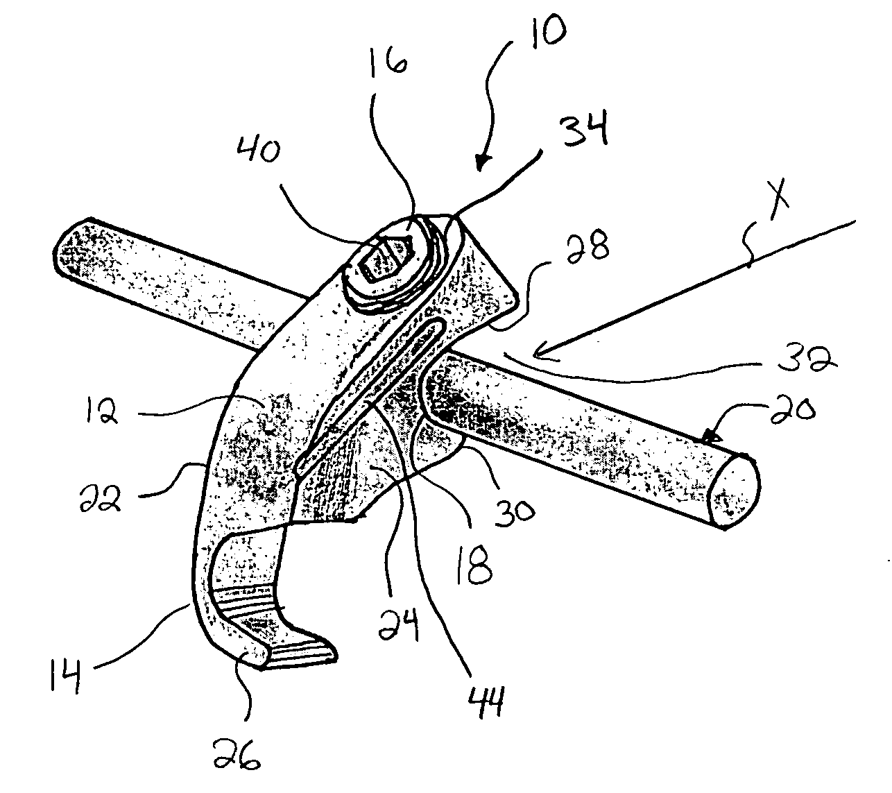
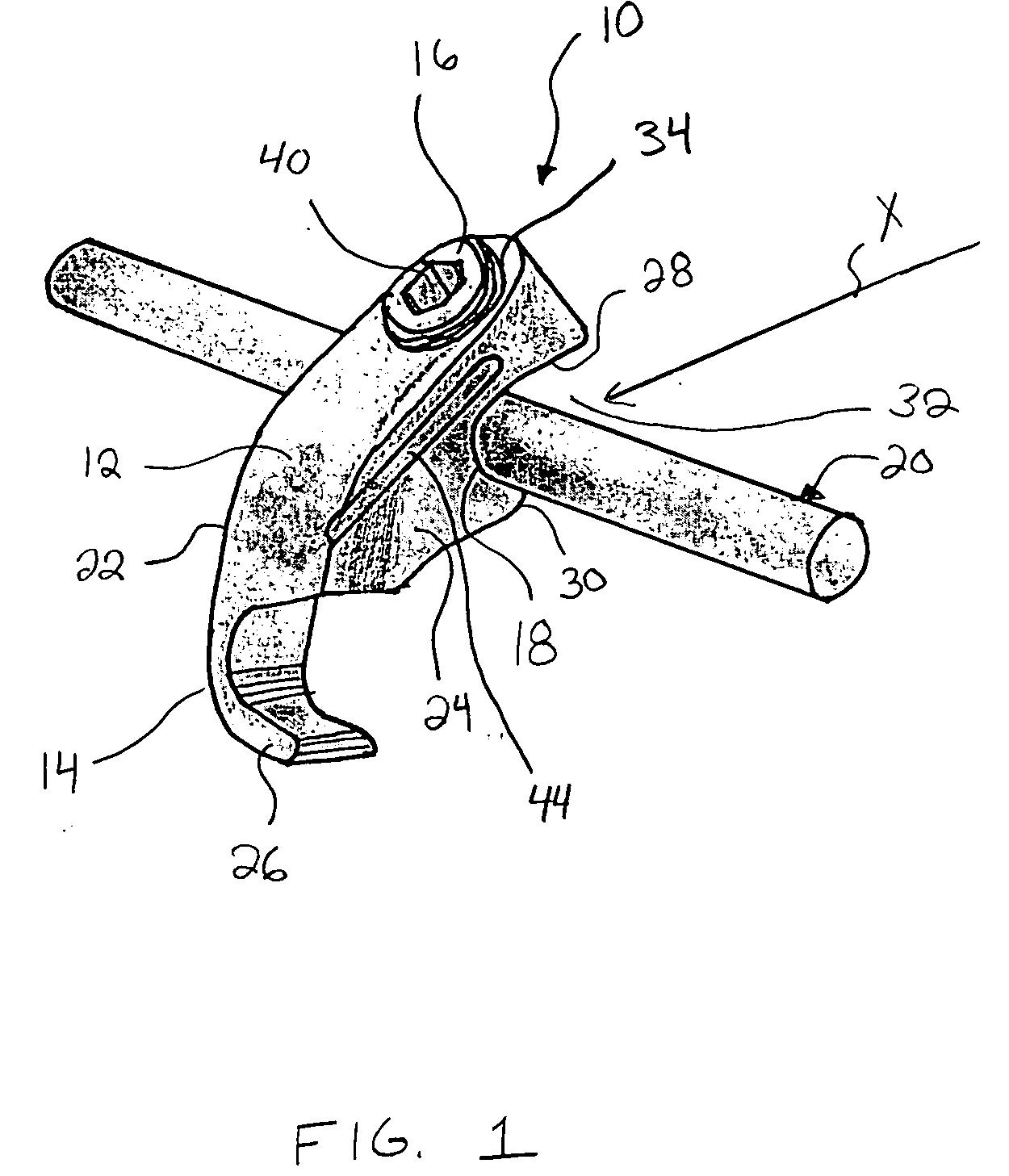
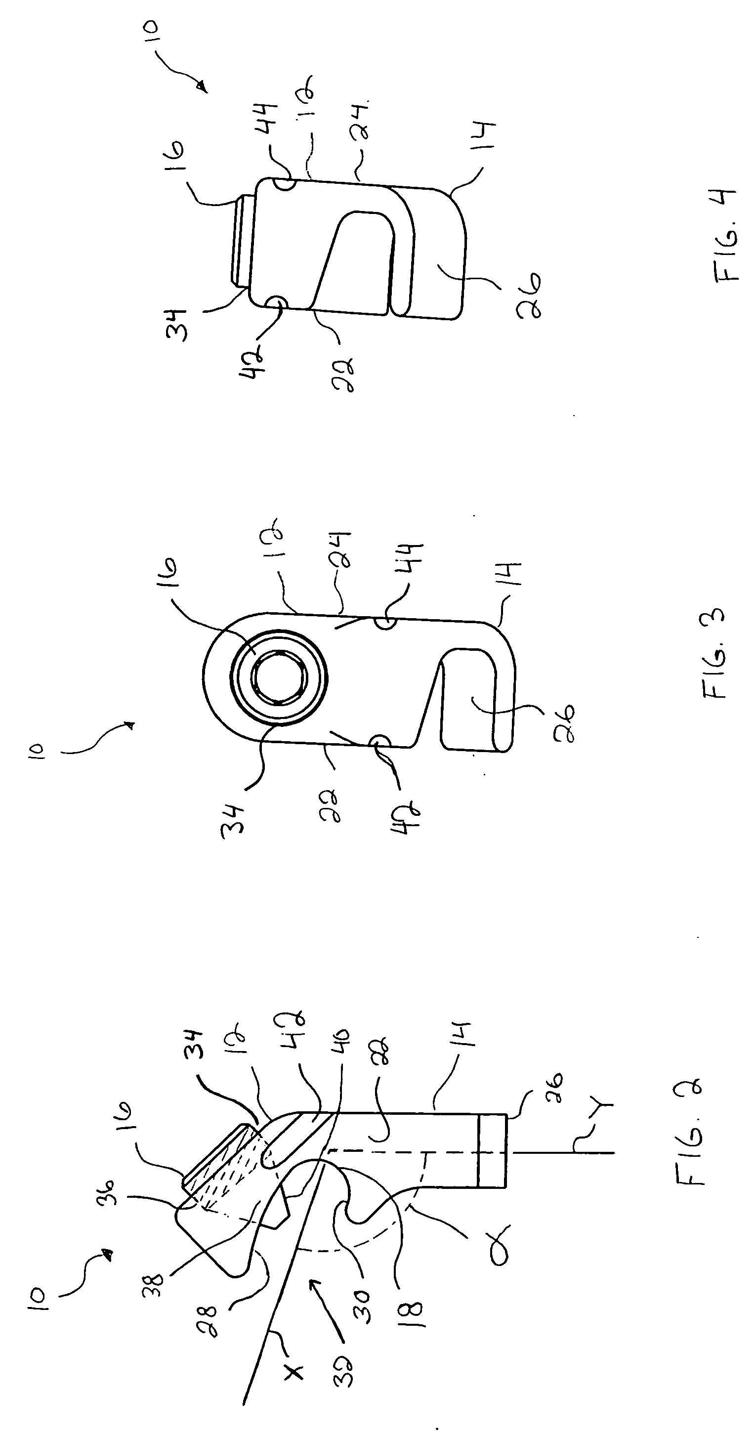
[0016] Referring to FIG. 1, a first illustrative embodiment of a spinal fixation device according to the present invention is shown attached to a spinal rod. The spinal fixation device, shown as spinal hook 10, generally includes a body 12, a hook 14 extending from the body 12, and a fastener 16 engaged with the body 12. Body 12 may define a rod-receiving channel 18 for receiving the spinal rod 20. In the illustrative embodiment of FIG. 1, hook 14 is attached at the left side of body 12 and extends to the right (as viewed in FIG. 1), and thus is called a “left” embodiment. The illustrative embodiment of FIGS. 2-4 is substantially identical to the embodiment of FIG. 1 except that it is a “right” embodiment, in that the hook 14 is attached at the right side of body 12 and extends to the left (as viewed in FIGS. 3 and 4). The right and left embodiments may be provided, for example, to allow spinal hooks 10 to be attached to a portion of a vertebra, such as a lamina, from both sides of ...


PUM


Abstract

The present invention is directed to a spinal fixation device. The device may include a body defining a channel for receiving a spinal rod, the channel having a first branch and a second branch separated by a lateral opening, a hook extending from the body for engaging a portion of a vertebra, and a fastener configured to secure the spinal rod in the channel. The fastener may extend through only the first branch. The spinal fixation device may also include one or more tool engagement recesses. Additionally, the present invention is directed to methods of spinal fixation.

Description

TECHNICAL FIELD OF THE INVENTION [0001] The present invention relates generally to spinal fixation devices and methods of spinal fixation. More specifically, the present invention relates to hooks for spinal fixation, and methods of spinal fixation using the same. BACKGROUND OF THE INVENTION [0002] There are many known spinal conditions that require the imposition and / or maintenance of corrective forces on the spine in order to return the spine to its normal condition. As a result, numerous systems have been developed for use in spinal fixation. One type of spinal fixation system generally includes one or more spinal rods placed parallel to the spine with fixation devices (such as hooks, screws, or plates) interconnected between the spinal rods and selected portions of the spine. One problem with some known spinal fixation devices is that they usually require the surgeon to insert the spinal rod onto the devices in the axial direction (i.e., in series), making it difficult for the s...

Claims


Application Information

Patent Timeline
IPC IPC(8): A61B17/28A61B17/70
CPCA61B17/2812A61B17/7056A61B17/7041A61B17/70
Inventor KEYER, THOMAS R.WALTHER, MARTIN
Owner SYNTHES USA
Why Eureka
Eureka Blog
Learn More