Protective tire shield

a technology for protecting tires and tires, applied in the field of steel tire cages, can solve problems such as internal damage of tires, and achieve the effect of preventing injury to tire technicians and improving the safety of tires

Inactive Publication Date: 2005-04-21
WHITE JOEL M
View PDF7 Cites 27 Cited by
  • Summary
  • Abstract
  • Description
  • Claims
  • Application Information

AI Technical Summary

Benefits of technology

[0004] It is an object of this invention to improve the safety of a tire cage. It is an object of this invention to prevent injury to tire technicians resulting from an air blast caused by an exploding tire. It is yet a further object of this invention to disclose an improved tire cage having a shield capable of protecting a technician from an air blast received from an exploding tire.
[0005] One aspect of this invention provides for a tire safety cage to protect a technician from an explosive air blast when inflating a wheel through its valve comprising: a frame having a front side, a back side, a top side and an end portion for entry of the wheel into the cage; a transparent shield positioned on an interior front side of the frame to allow for convenient inspection of the wheel after the wheel is inflated, and to prevent the explosive air blast from passing through the front side of the cage to the technician; and, a central opening through the shield to allow the technician to access the valve on the wheel.

Problems solved by technology

Apparently the tire had been internally damaged when it had been driven with insufficient pressure.
However, the air blast—of some 30,000 pounds—passed through the cage and knocked him over.

Method used


Image

  • Protective tire shield
  • Protective tire shield

Examples


Embodiment Construction

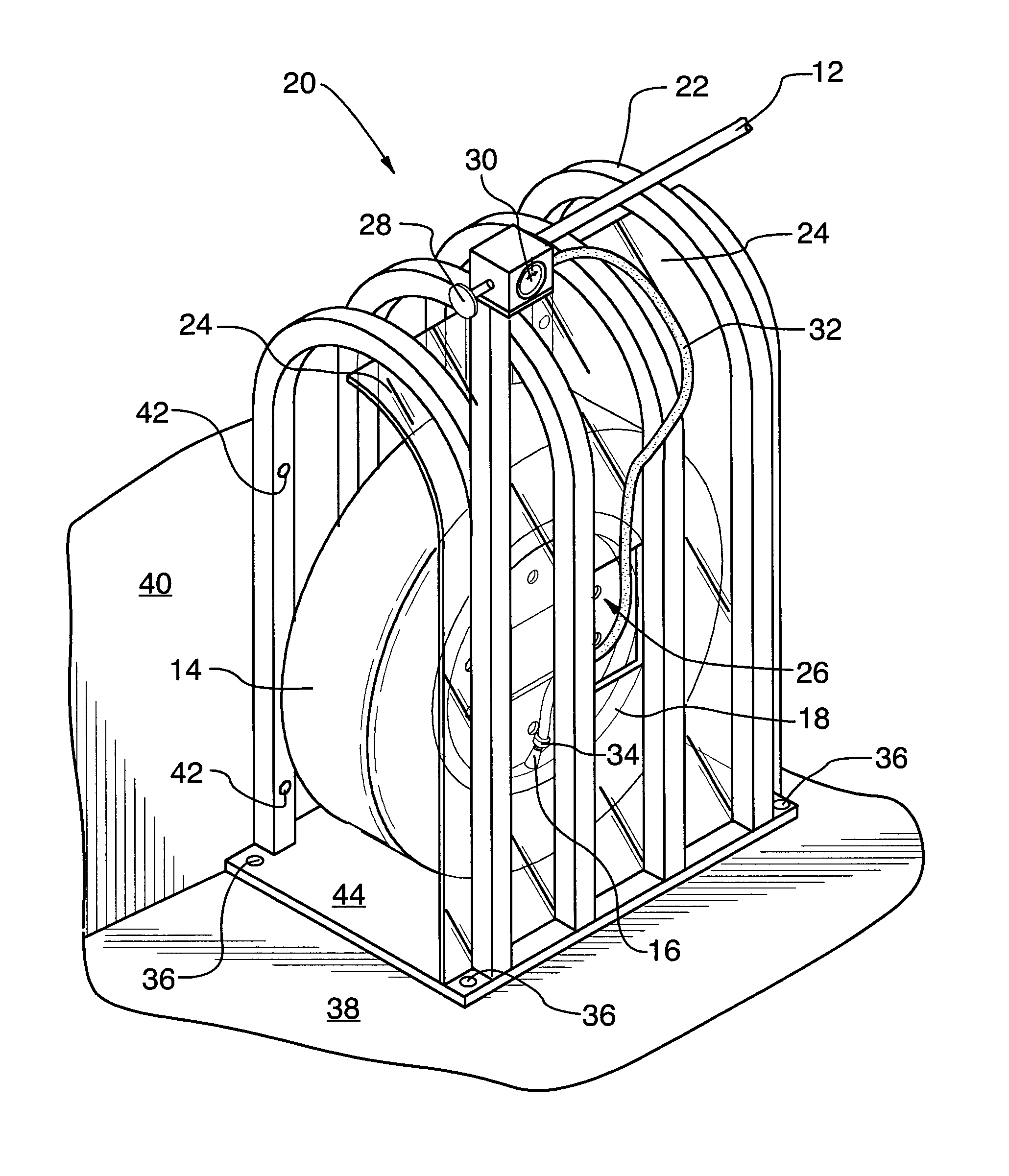
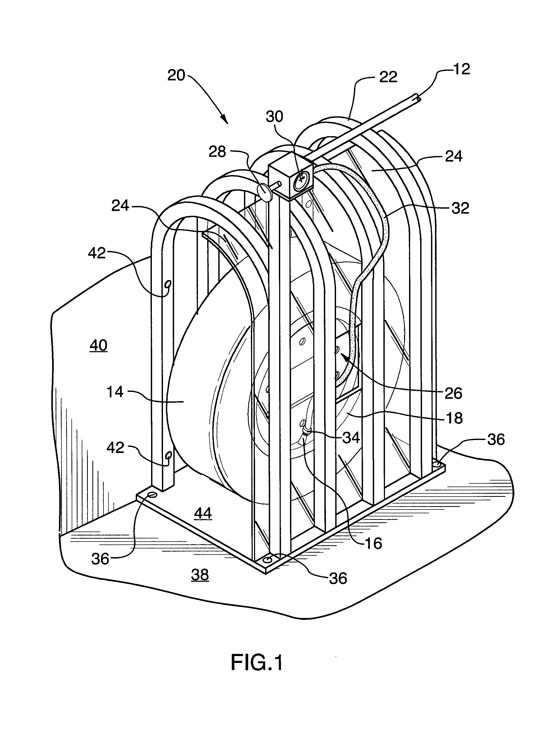
[0011] Turning now to the drawings and more particularly to FIG. 1 we have a perspective view of a wheel 18 positioned in a tire cage 20. The tire safety cage 20 protects a technician from an explosive air blast when inflating the wheel 18 through its valve 16. The tire cage comprises: a frame 22 having a front side, a back side, a top side and an end portion for entry of the wheel 18 into the cage 20; a transparent shield 24 positioned on an interior front side of the frame to allow for convenient inspection of the wheel 18 after it is inflated, and to prevent the explosive air blast from passing through the front side of the cage 20 to the technician; and, a central opening 26 through the shield 24 to allow the technician to access the valve 16 on the wheel 18.

[0012] In a preferred embodiment of the invention the cage 20 further comprises a pressure regulator 28 having an air pressure gauge 30 which are carried by the frame 22. The pressure regulator 28 has a low pressure air hos...


PUM


Abstract

The apparatus which protects from an explosive air blast when inflating a wheel comprises: a frame having a front side, a back side, a top side and an end portion for entry of the wheel into the cage; a transparent shield positioned on an interior front side of the frame to allow for convenient inspection of the wheel after the wheel is inflated, and to prevent the explosive air blast from passing through the front side of the cage to the technician; and, a central opening through the shield to allow the technician to access the valve on the wheel. The apparatus can be adapted to be anchored to a supporting structure so that in the event of an explosion the cage will remain stationary. A method of inflating a tire on a comprises the steps of: a) providing a tire safety cage as above; b) rolling the wheel to be inflated into the cage; c) accessing the valve on the wheel with an air hose through the central opening in the shield and inflating the tire to required air pressure; d) observing the pressurized wheel in the cage through the shield for a period of time to ensure that the tire will safely hold air; and finally, e) rolling the wheel out of the cage.

Description

FIELD OF THE INVENTION [0001] This invention relates to steel tire cages used for safety when inflating truck tires. More particularly this invention relates to a tire safety cage having a front transparent shield to protect a tire technician from a tire or wheel explosion. BACKGROUND OF THE INVENTION [0002] Medium size truck tires are normally inflated to a pressure of 100 psi. When a tire is inflated generally accepted safety procedures mandate positioning the wheel inside a tire safety cage prior to inflating it to pressure. Tire cages are used to prevent serious injury or damage to property in the event of a tire failure and explosion. [0003] The inventor herein suffered 4 broken bones and 14 stitches on his face when he inflated a tire in a safety cage. The side wall of the tire failed. Apparently the tire had been internally damaged when it had been driven with insufficient pressure. The safety cage prevented the tire from striking him. However, the air blast—of some 30,000 po...

Claims


Application Information

Patent Timeline
Patent Type & Authority Applications(United States)
IPC IPC(8): B60C25/00B60S5/04
CPCB60S5/04B60C25/147
Inventor WHITE, JOEL M.
Owner WHITE JOEL M
Why Eureka
Try Eureka