
Child-resistant trigger sprayer

a technology of trigger sprayer and trigger lever, which is applied in the direction of liquid handling, closure using stoppers, instruments, etc., can solve the problems that the actuation of the trigger lever could produce a minor amount of unwanted discharge or leakage, and the minor discharge or leakage remains an unacceptable feature of many trigger sprayers, so as to enhance the child-resistant properties of the assembly

Active Publication Date: 2005-04-21
SILGAN DISPENSING SYST CORP
View PDF23 Cites 28 Cited by
  • Summary
  • Abstract
  • Description
  • Claims
  • Application Information

AI Technical Summary

Benefits of technology

The invention is a child-resistant trigger sprayer that requires a minimum two-step process before enabling trigger actuation. The sprayer includes a pump body, a discharge nozzle, and a trigger lever. A trigger cover is mounted on the sprayer and can be rotated between open and closed positions. The trigger cover can be locked in the open position to prevent accidental triggering. The sprayer also includes a detent and a notch in the cap for easy unlocking. The invention solves the problem of prior art trigger sprayers being easily accessible to children and provides a safer alternative for spraying toxic or harmful fluids.

Problems solved by technology

For some residual quantity of liquid remaining within the nozzle, even in the discharge closed position, actuation of the trigger lever could produce a minor amount of unwanted discharge or leakage.
From a child safety viewpoint, for toxic or poisonous liquids, this minor discharge or leakage nevertheless remains an unacceptable feature of many of the trigger sprayers presently on the market.
However, this design has drawbacks in that a simple one-step process of rotating the cover to expose the trigger is required to render the trigger operational.

Method used


Image

  • Child-resistant trigger sprayer
  • Child-resistant trigger sprayer
  • Child-resistant trigger sprayer

Examples


Embodiment Construction

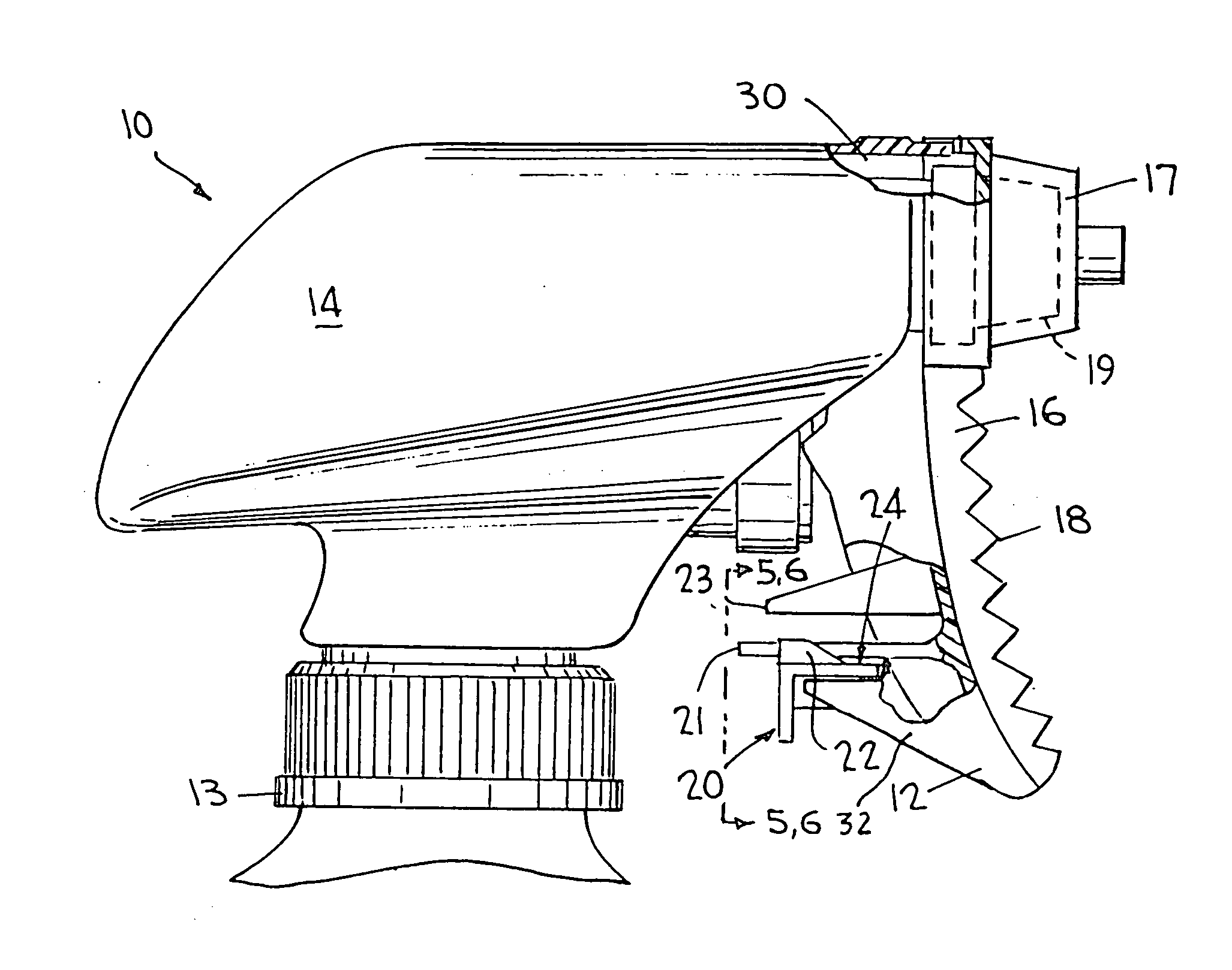
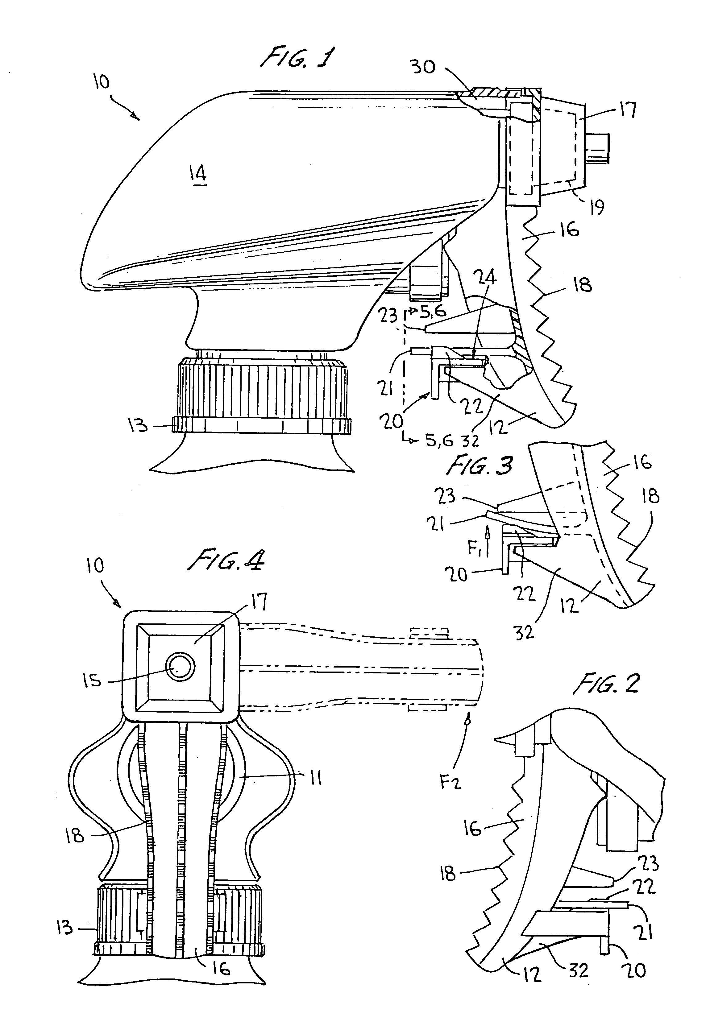
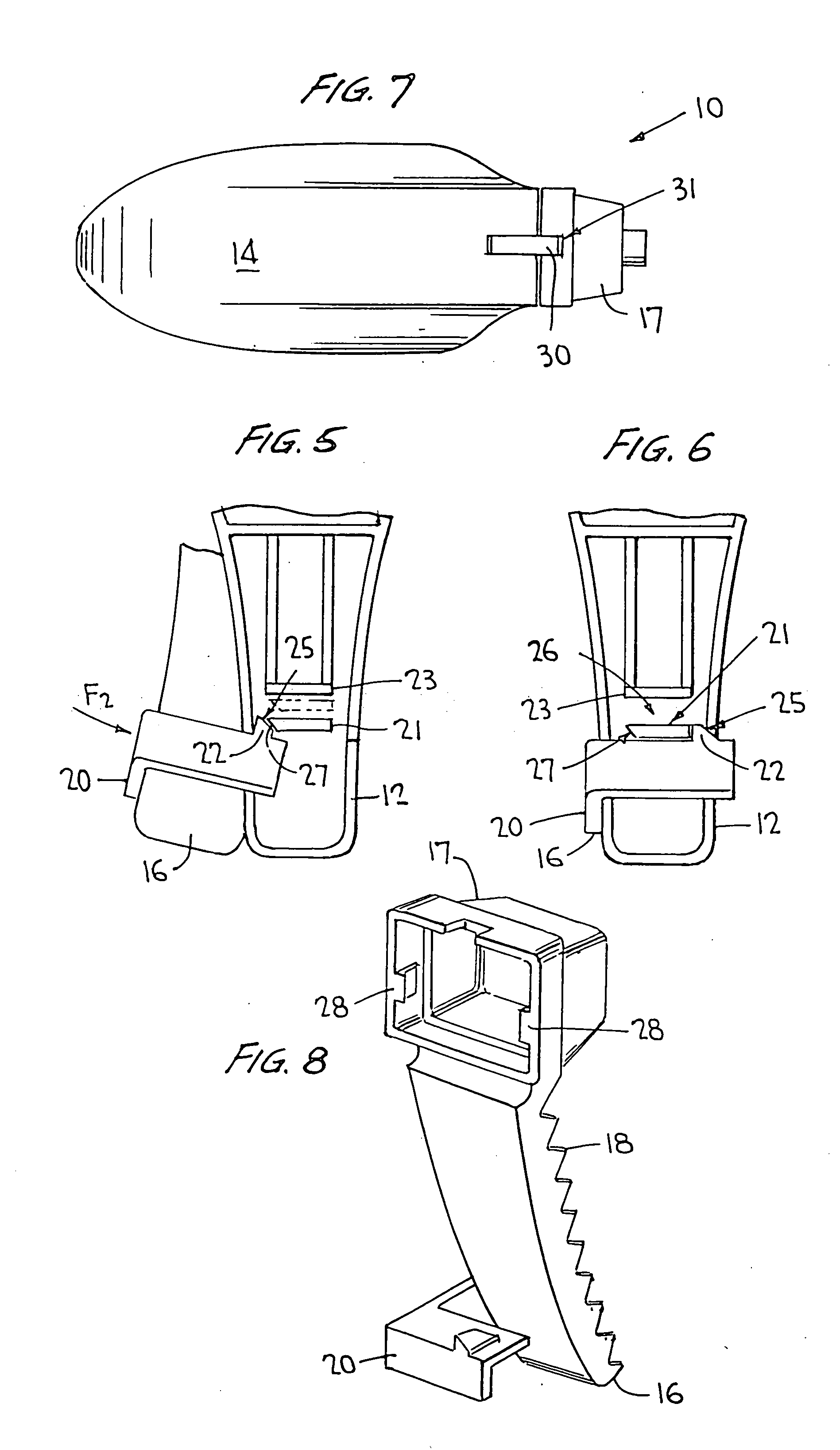
[0026] Referring now to the drawings wherein like reference numerals designate corresponding parts throughout the several views, FIGS. 1-8 illustrate a child-resistant trigger sprayer (hereinafter trigger sprayer) according to the present invention, generally designated 10.

[0027] As shown in FIGS. 1 and 4, trigger sprayer 10 may include a pump body with a pump piston (not shown) reciprocating within a pump cylinder 11 of the pump body, a trigger lever 12 movably mounted to the pump body with its top in engagement with the pump piston for the reciprocation thereof upon manual squeeze of the trigger as in a manner known in this art. The trigger sprayer may be structured for operation essentially the same as that disclosed in U.S. Pat. No. 5,114,049, commonly owned herewith and the disclosure of which is incorporated herein by reference. A container closure 13, which may be internally threaded, may be coupled to the pump body for mounting trigger sprayer 10 to the neck of a container ...


PUM


Abstract

A trigger actuated liquid sprayer, including a pump body, a discharge nozzle mounted on a forward end of the body for manual rotation about a central axis thereof between discharge open and closed positions, and a trigger lever movably mounted to the body for operating a pumping mechanism upon actuation thereof. A trigger cover may be mounted on the sprayer and overlie a front face of the trigger lever in a first position for immobilizing trigger lever actuation. The trigger cover may be rotatable to a second position from the first position for exposing the front face for facilitating a grasp of the trigger lever for manual actuation thereof for operating the pumping mechanism. The trigger cover may be latched with the trigger lever in the first position to prevent rotation of the trigger cover from the first position to thereby render the sprayer child-resistant.

Description

BACKGROUND OF INVENTION [0001] a. Field of Invention [0002] The invention relates generally to a trigger actuated pump sprayer, and more particularly to such a sprayer having a trigger lock rendering the sprayer child-resistant. [0003] b. Description of Related Art [0004] The trigger actuated sprayer of known variety typically has a spray nozzle rotatable about its central axis between discharge open and closed positions. There may be two open and two intervening closed positions such that from a given closed position, the nozzle is capable of being rotated 90° in either direction to an open position and vice-versa. [0005] When the nozzle is in the discharge closed or OFF positions, although the sprayer is designed such that product is not intended to discharge from the nozzle under these circumstances, the trigger lever is nevertheless capable of being actuated to a certain extent. For some residual quantity of liquid remaining within the nozzle, even in the discharge closed positi...

Claims


Application Information

Patent Timeline
Patent Type & Authority Applications(United States)
IPC IPC(8): B05B11/00B65D47/34B65D83/76B67D7/58
CPCB05B11/3059B05B11/3057B05B11/1059B05B11/1057B65D47/00
Inventor GOOD, ROBERT J.SWEETON, STEVEN L.
Owner SILGAN DISPENSING SYST CORP
Learn More