System and method for providing redundant routing capabilities for a network node

a network node and routing capability technology, applied in the field of network technology, can solve the problems of affecting the performance of the system, and changing the preference of routing,

Inactive Publication Date: 2005-04-21
IP INFUSION INC
View PDF32 Cites 314 Cited by
  • Summary
  • Abstract
  • Description
  • Claims
  • Application Information

AI Technical Summary

Benefits of technology

[0004] Dynamic routing occurs when routing devices talk to adjacent routing devices, informing each other of what network each routing device is currently connected to. The routing devices must communicate using a routing protocol that is running by an application instantiating the routing function, or a routing daemon. In contrast to a static protocol, the information placed into the routing tables—the routes—are added and deleted dynamically by the routing daemon as the routes messages take in the system change over time. Additionally, other changes can occur to the routing information over time. For example, route preferences can change due to changes in network conditions such as delays, route addition / deletions, and network reachability issues.

Problems solved by technology

For example, route preferences can change due to changes in network conditions such as delays, route addition / deletions, and network reachability issues.
Thus, a change in a network topology typically impacts the performance of the system.
First, when a link goes down, the other routing devices must determine that the link has ceased to operate.
In addition to link failures, changes may also be precipitated by such events as node failures, or network failures.
Again, this may entail effort in the form of determining metrics for routes associated with the again-operational link as well as rebuilding any internal routing tables at the neighboring nodes or routing devices upon the reinstantiation of service of the routing device at a node that the routing device services.
However, in this case, the failure of the first device to respond to network traffic and / or routing configuration requests may cause the other routing devices in the network to determine that the routing device associated with a node that is no longer reachable.
Based upon the new values available to the neighboring routing device, these neighboring routing devices may have to recalculate routing costs and rebuild their internal routing tables.
Further, upon receipt of the new values associated with the “new” connection to the now functioning backup routing device, the other routing devices in the defined network may then also have to recalculate routing costs and rebuild their routing tables.
During synchronization operations, however, a variety of complex messages can be exchanged, depending on the event that occurred, the state of the database, and other factors.
If a new routing device is brought online, however, that routing device will have to discover all the routing devices, networks and interfaces within its area, and this process can consume a significant amount of network resources.
This database-synchronization model represents what is perhaps the greatest challenge with running dynamic routing mechanisms in large, complex networks, since a significant amount of time can be spent maintaining database synchronization in the face of network stability problems.

Method used


Image

  • System and method for providing redundant routing capabilities for a network node
  • System and method for providing redundant routing capabilities for a network node
  • System and method for providing redundant routing capabilities for a network node

Examples


Embodiment Construction

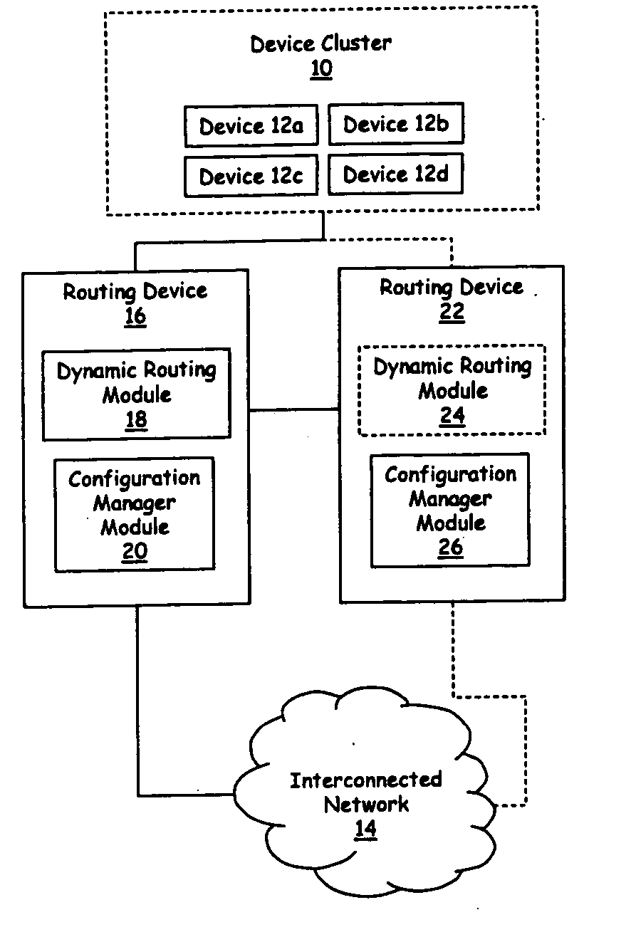
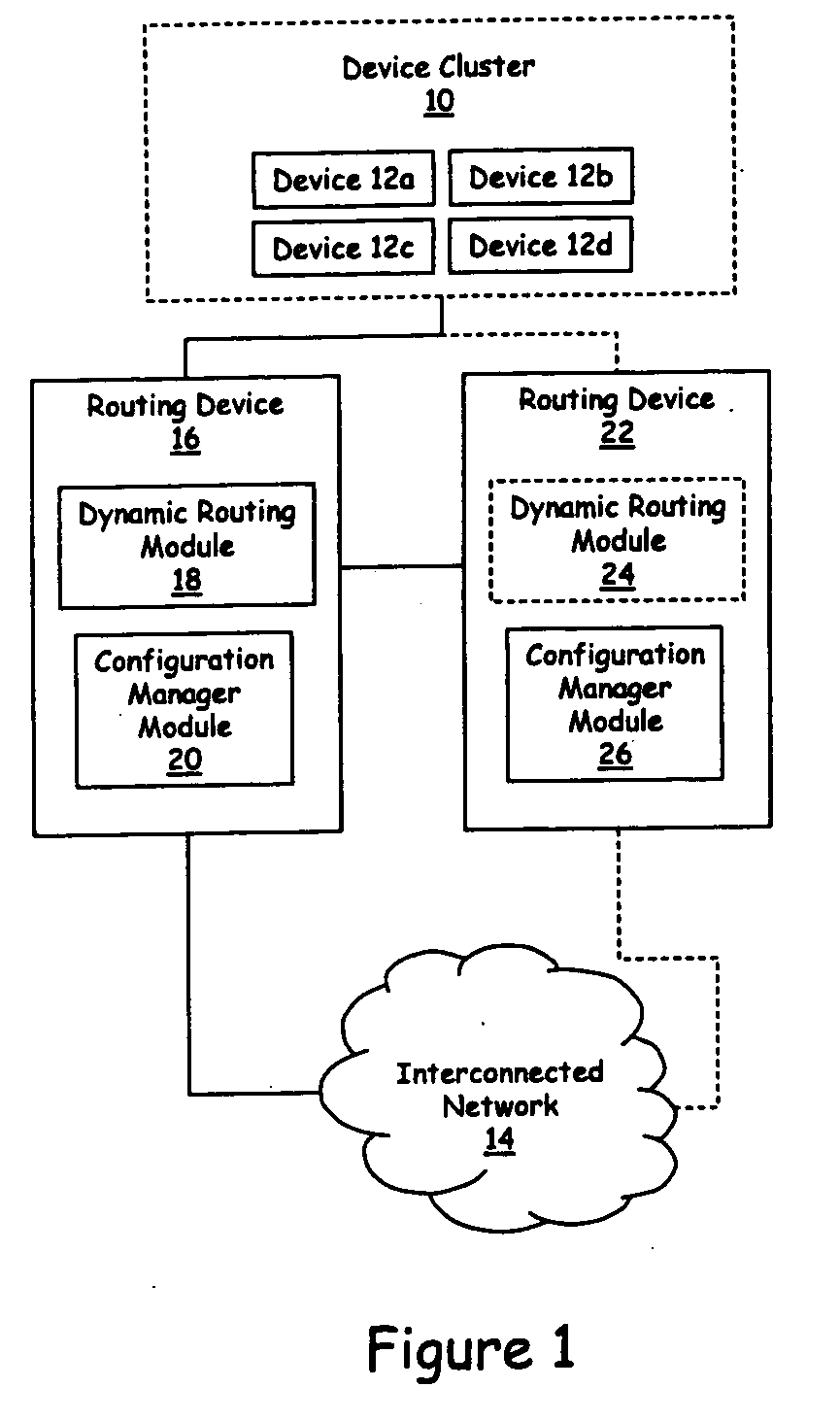
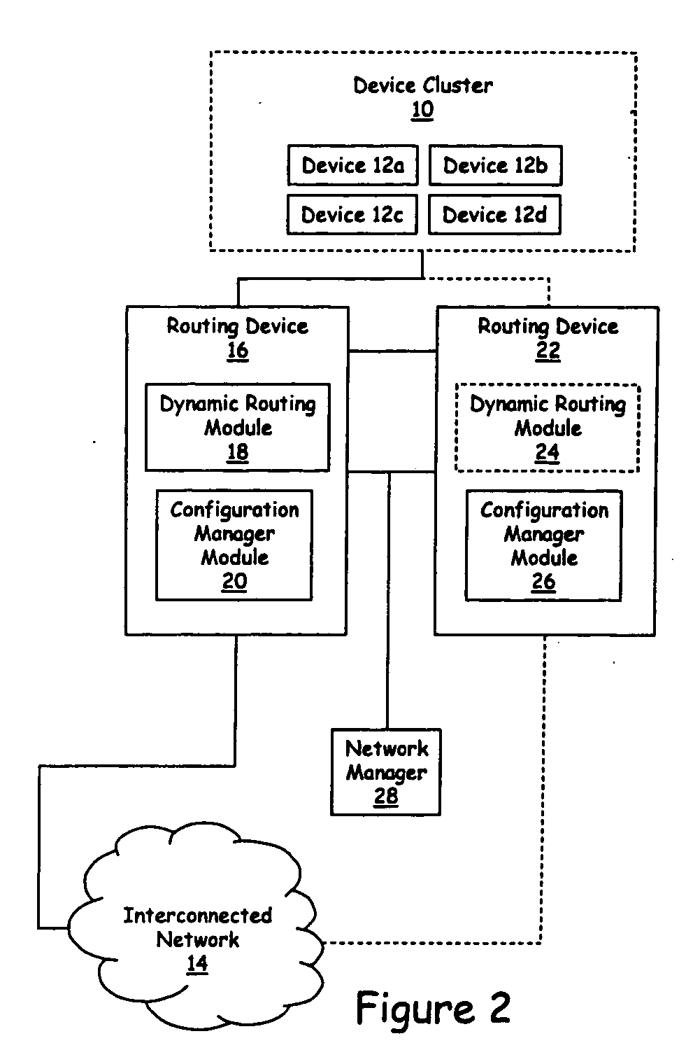
[0032] Embodiments of the present invention are described herein in the context of a system and method for providing redundant routing capabilities for a network node. Those of ordinary skill in the art will realize that the following detailed description of the present invention is illustrative only and is not intended to be in any way limiting. Other embodiments of the present invention will readily suggest themselves to such skilled persons having the benefit of this disclosure. Reference will now be made in detail to implementations of the present invention as illustrated in the accompanying drawings. The same reference indicators will be used throughout the drawings and the following detailed description to refer to the same or like parts.

[0033] In the interest of clarity, not all of the routine features of the implementations described herein are shown and described. It will, of course, be appreciated that in the development of any such actual implementation, numerous impleme...


PUM


Abstract

A routing device that provides redundancy for a node is envisioned. The routing device has a dynamic routing module operable to start functioning at a particular time. A configuration manager is provided. The configuration manager is coupled to a second routing device and stores configuration information associated with operational characteristics of a dynamic routing module associated with the second routing device. A network information module stores routing information from the second routing device. The dynamic routing module is executed upon an indication that the second dynamic routing device is no longer operating, and the configuration device configures the dynamic routing module according to the stored configuration information.

Description

BACKGROUND [0001] 1. Field of the Invention [0002] The present invention is directed to networking technology. In particular, the invention is directed to providing a backup service to a group of computing devices located within a logical space. [0003] 2. Background [0004] Dynamic routing occurs when routing devices talk to adjacent routing devices, informing each other of what network each routing device is currently connected to. The routing devices must communicate using a routing protocol that is running by an application instantiating the routing function, or a routing daemon. In contrast to a static protocol, the information placed into the routing tables—the routes—are added and deleted dynamically by the routing daemon as the routes messages take in the system change over time. Additionally, other changes can occur to the routing information over time. For example, route preferences can change due to changes in network conditions such as delays, route addition / deletions, and...

Claims


Application Information

Patent Timeline
Patent Type & Authority Applications(United States)
IPC IPC(8): H04L12/56
CPCH04L45/00H04L45/586H04L45/28H04L45/851H04L45/56
Inventor MAY, ROBERT ALVIN
Owner IP INFUSION INC
Why Eureka
Try Eureka