Wireless communication using multi-transmit multi-receive antenna arrays

a multi-receiver, antenna array technology, applied in multiplex communication, electromagnetic wave modulation, baseband system details, etc., can solve the problems of complex receivers and limited range of operational snrs

Active Publication Date: 2005-04-21
GOOGLE TECH HLDG LLC
View PDF4 Cites 34 Cited by
  • Summary
  • Abstract
  • Description
  • Claims
  • Application Information

AI Technical Summary

Problems solved by technology

However, multi-stream schemes of this kind that have been proposed are viable only at high SNRs and require complex receivers (for a N-Transmit and M-Receive antenna configuration, M must be greater than or equal to N) in order to be able to extract the different transmitted signals at the receiver.
Such schemes are limited by compromises between diversity gain and spectral efficiency and accordingly the range of operational SNRs is limited unless complexity is increased or high modulation constellations (for example greater than 64 QAM) are used.

Method used


Image

  • Wireless communication using multi-transmit multi-receive antenna arrays
  • Wireless communication using multi-transmit multi-receive antenna arrays
  • Wireless communication using multi-transmit multi-receive antenna arrays

Examples


Embodiment Construction

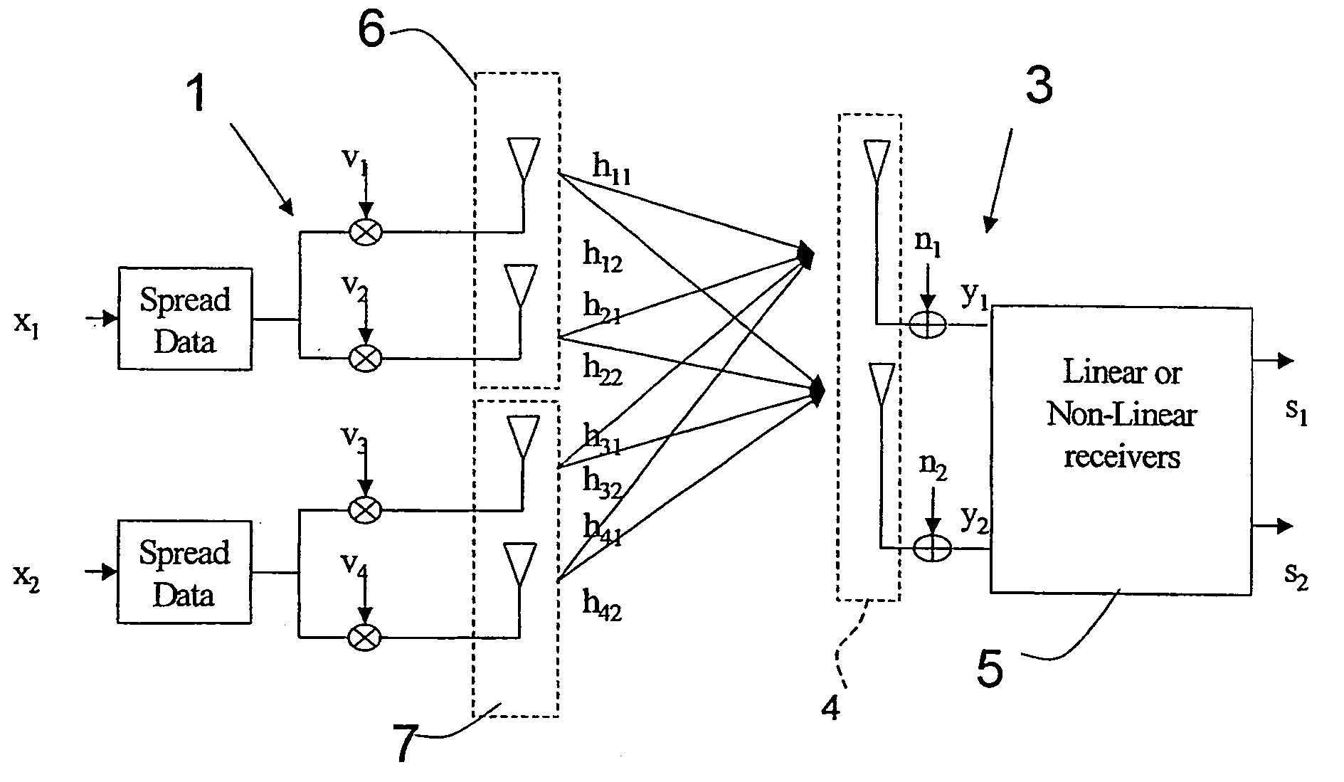
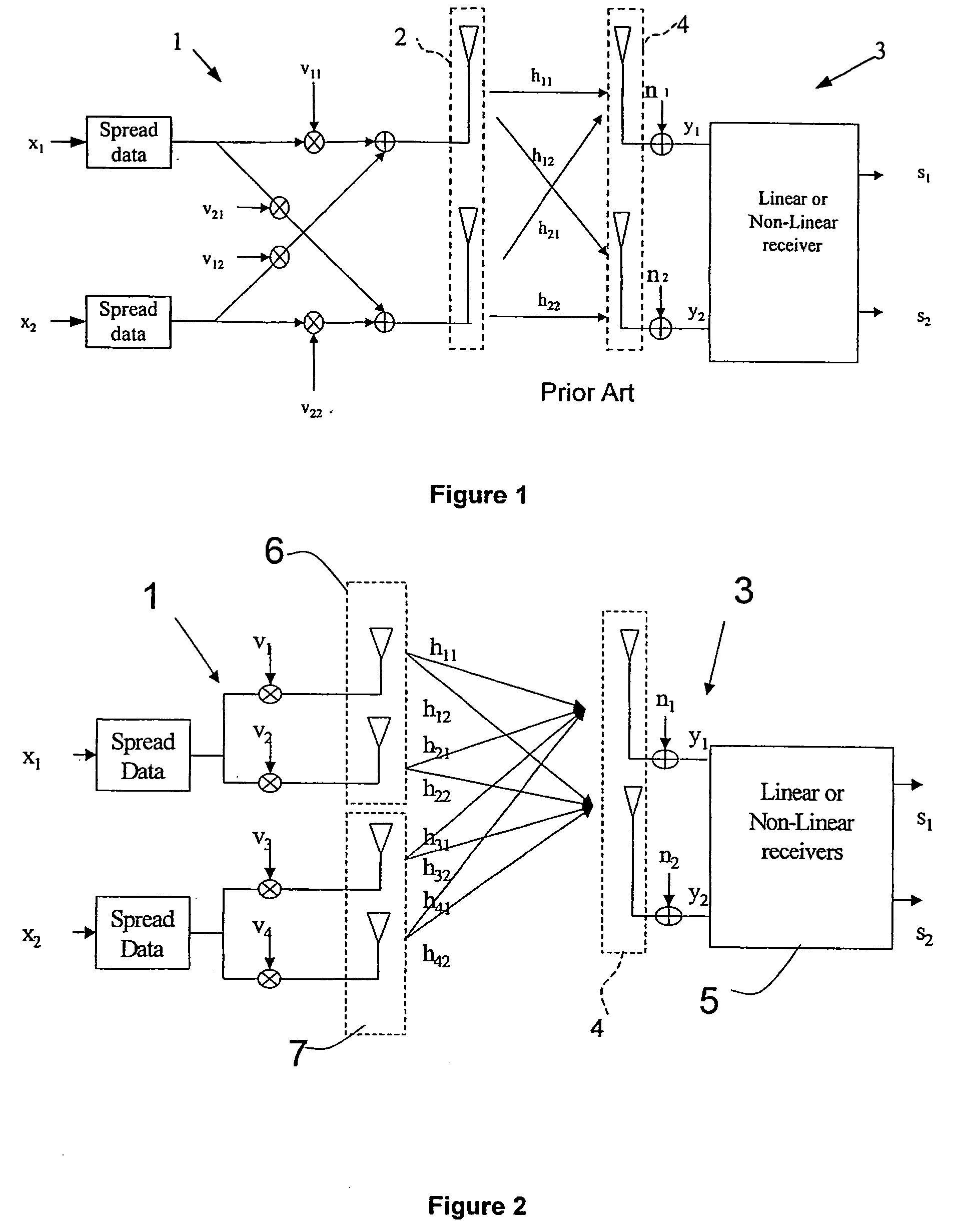
[0017]FIG. 1 of the drawings shows a known multi-stream wireless communication system comprising a transmitter station 1 comprising a transmit antenna array 2 of N transmit antenna elements and a receiver station 3 comprising a receive antenna array 4 of M receive antenna elements. In the example illustrated in FIG. 1, N=M=2. A plurality of distinct data streams x1 to XF (F=two in the example of FIG. 1) are transmitted from the transmit antenna array 2 to the receive antenna array 4 and the data streams are weighted by respective complex weighting coefficients vn,f where n is the nth transmit antenna element and f is the fth data stream before being applied to the transmit antenna array. The distinct data streams are separated and estimated at the receiver station in a linear or non-linear receiver 5, to produce detected signals s1 and s2.

[0018] In the case shown in FIG. 1, with N=M=F=2, the propagation channel can be represented by a matrix H_=[h_11h_12h_21h_22].

In the closed-lo...


PUM


Abstract

A method of closed-loop multi-stream wireless communication between a transmitter (1) comprising a transmit antenna array of N transmit antenna elements and a reciever (3) comprising a receive antenna array (4) of M receive antenna elements, wherein a plurality of distinct data steams (x1 X2) are transmitted from the transmit antenna array to the receive antenna array and the data streams are weighted by respective complex weighting matcices before being applied to the transit antenna array. The distinct data steams are separated and estimated at the reciever. The distinct data streams (x1 xG) are applied to respective sub-groups (6, 7) of the transmit antenna elements at least one of which comprises a plurality of the transmit antenna elements each of the sub-groups comprising at least Nd transmit antenna elements, where M is greater than or equal to (N / Nd). The complex weighting matrices (v1 to vn) are functions of the respective transmission channels (hij) of the data streams (x1, to xG) including the respective sub-groups of transmit antenna elements. Nd is preferably greater than or equal to two. Each of the complex weighting matrices is calculated to be substantially equal to the eigenvector corresponding to the largest eigenvalue of the matirx H H, where H is the matrix of the equvalent channel including the respective sub-groups of transmit antenna elements (6, 7) seen by the corresponding data stream HH is the Hermitian transform of the matrix H. The number of the transmit antenna elements in each of the sub-groups is preferablly re-configurable during operation as a function of channel conditions.

Description

FIELD OF THE INVENTION [0001] This invention relates to wireless communication using multi-transmit multi-receive antenna arrays, that is to say where both the transmitting and the receiving station comprise an array of antenna elements. In cases where the antenna elements at a given station may be used both for transmission and for reception, references herein to a ‘transmitter’, a ‘transmit antenna’ a ‘receiver’ or a ‘receive antenna’ are to be construed as references to the function that they are exercising during that operation. BACKGROUND OF THE INVENTION [0002] Wireless communication systems are assuming ever-increasing importance for the transmission of data, which is to be understood in its largest sense as covering speech or other sounds and images, for example, as well as abstract digital signals. [0003] Currently proposed standards for wireless communication systems include the 3GPP (3rd generation Partnership Project) and 3GPP2 standards, which use Code Division Multiple...

Claims


Application Information

Patent Timeline
Patent Type & Authority Applications(United States)
IPC IPC(8): H04B7/04H04B7/06H04J99/00H04L25/02H04L25/03
CPCH04B7/0413H04L25/03343H04L25/0228H04B7/0615H04B7/06
Inventor BULJORE, SOODESHVIALLE, SANDRINEWHINNETT, NICHOLAS
Owner GOOGLE TECH HLDG LLC
Why Eureka
Try Eureka