Wood-concrete-composite systems

Inactive Publication Date: 2005-04-28
BATHON TOBIAS +1
View PDF17 Cites 36 Cited by
  • Summary
  • Abstract
  • Description
  • Claims
  • Application Information

AI Technical Summary

Benefits of technology

[0012] To the surprise of the inventors, it was detected that the composite action can even be increased by connecting two ends of the connection device into t

Problems solved by technology

This uncoupling does however not reduce the composite action between wood and con

Method used


Image

  • Wood-concrete-composite systems
  • Wood-concrete-composite systems
  • Wood-concrete-composite systems

Examples


Embodiment Construction

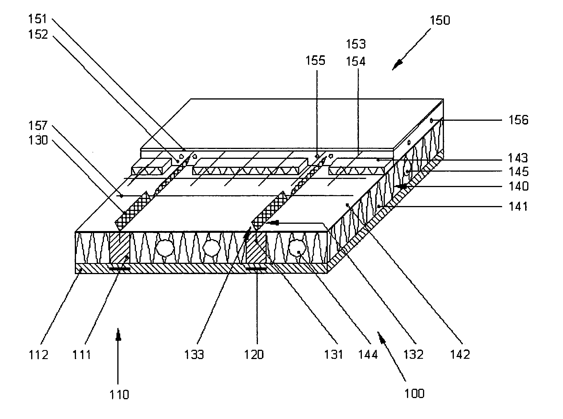
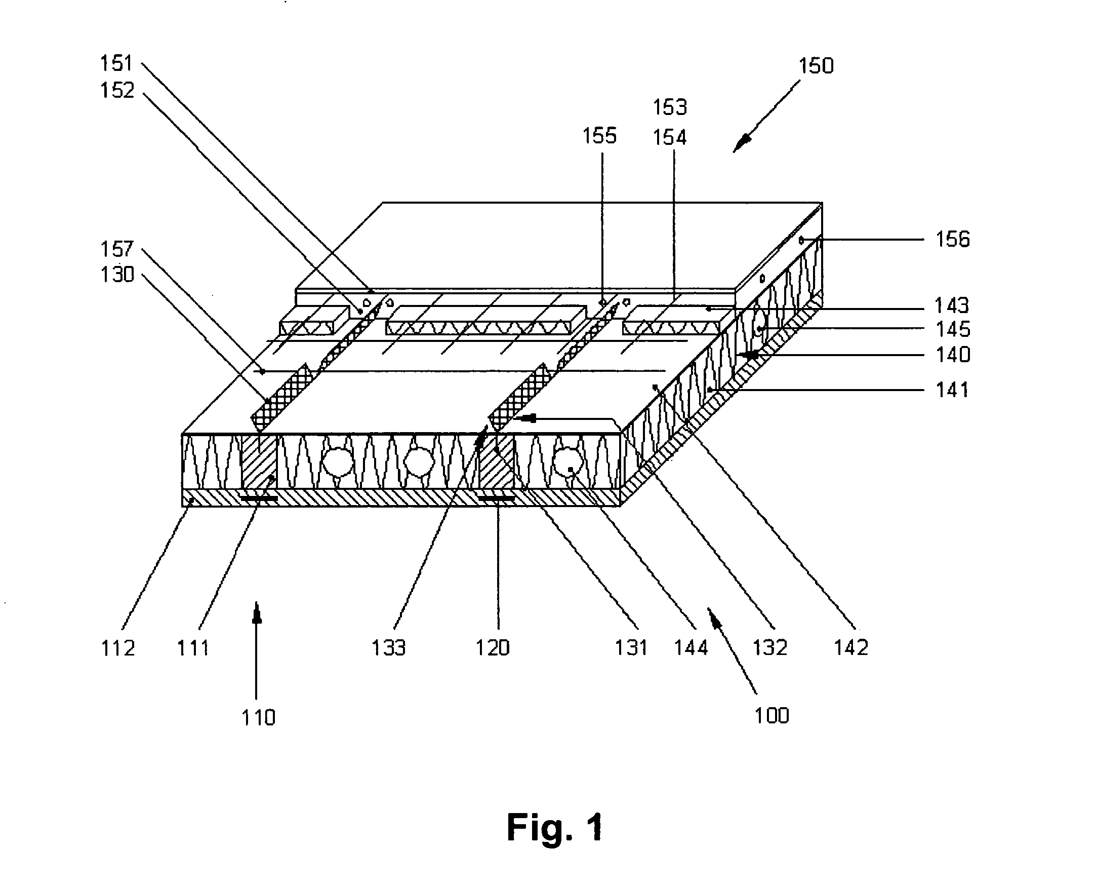
[0017] The wood concrete composite system according to this invention includes wooden construction components, a (at least) on one side bordering concrete construction unit and a (at least) single intermediate layer that creates at least a partial separation and / or uncoupling between the materials wood and concrete. The purpose of the intermediate layers is to (at least) partly separate and / or uncouple the wood and concrete in geometry, mechanics and / or physical (i.e. thermal, sound, vibration) performance. This uncoupling does however not reduce the composite action between wood and concrete substantially, since otherwise an economical solution is not to be obtained.

[0018] The rigid connection between the wood and concrete is achieved by gluing at least one end of the connecting devices into the wooden construction components. The other end reaches trough the intermediate layer and rests rigidly into the concrete section by mechanical friction after the curing of the concrete.

[00...


PUM

PropertyMeasurementUnit
Weightaaaaaaaaaa
Mechanical propertiesaaaaaaaaaa
Thermal propertiesaaaaaaaaaa

Abstract

A wood concrete composite system (100,200) has a wood construction component (110, 111, 112, 210, 211), at least single intermediate layer (140, 141, 142, 143, 230, 231, 232) and a concrete construction unit (150, 151, 152, 240, 241). The concrete construction unit (150, 151, 152, 240, 241) faces at least with one side towards the wood construction component (110, 111, 112, 210, 211). The at least single intermediate layer (140, 141, 142, 143, 230, 231, 232) creates at least a partial uncoupling between the wood and concrete.

Description

BACKGROUND OF THE INVENTION [0001] This invention relates to wood concrete composite system, which includes at least one wooden specimen, and a concrete specimen. [0002] The patent DE 44 06 433 C2, the content of which is incorporated herein by reference, presents wood with inserted bonded shaped parts to connect with materials of any kind. The known connection system is a flat body in form of a steel sheet, which is bonded partially into a wooden specimen and partially reaches out of the wooden specimen. The exposed section of the connection system serves to connect to further material. [0003] From the disclosure writing DE 198 08 208 A1, the content of which is incorporated herein by reference, it is known to connect wood to concrete by glued in shaped parts. The known wood concrete composite connection includes flat bodies in form of a steel sheet, which are bonded with one end into a slot brought into the wood and reaches over the wooden surface with the other end. The exposed e...

Claims


Application Information

Patent Timeline
IPC IPC(8): E04B5/02E04B5/12E04B5/23E04B5/38E04B5/48E04C1/39E04C1/40E04C1/41E04C2/26E04C2/296E04C2/52E04C3/29E04C3/46E04C5/07
CPCE04B5/04E04B5/12E04B5/23E04B5/38E04B5/48E04C5/07E04C2/26E04C2/296E04C2/52E04C3/29E04B2005/237E04B5/02
Inventor BATHON, TOBIASBATHON, LEANDER
Owner BATHON TOBIAS
Why Eureka
Try Eureka