Wood-drilling apparatus

Inactive Publication Date: 2005-04-28
LIU HSU HSIU KWEI +1
View PDF10 Cites 54 Cited by
  • Summary
  • Abstract
  • Description
  • Claims
  • Application Information

AI Technical Summary

Problems solved by technology

However, this requires different pairs of cylinders for wooden workpieces of different thickness since the cylinders 3 cannot be moved vertically.

Method used


Image

  • Wood-drilling apparatus
  • Wood-drilling apparatus
  • Wood-drilling apparatus

Examples


first embodiment

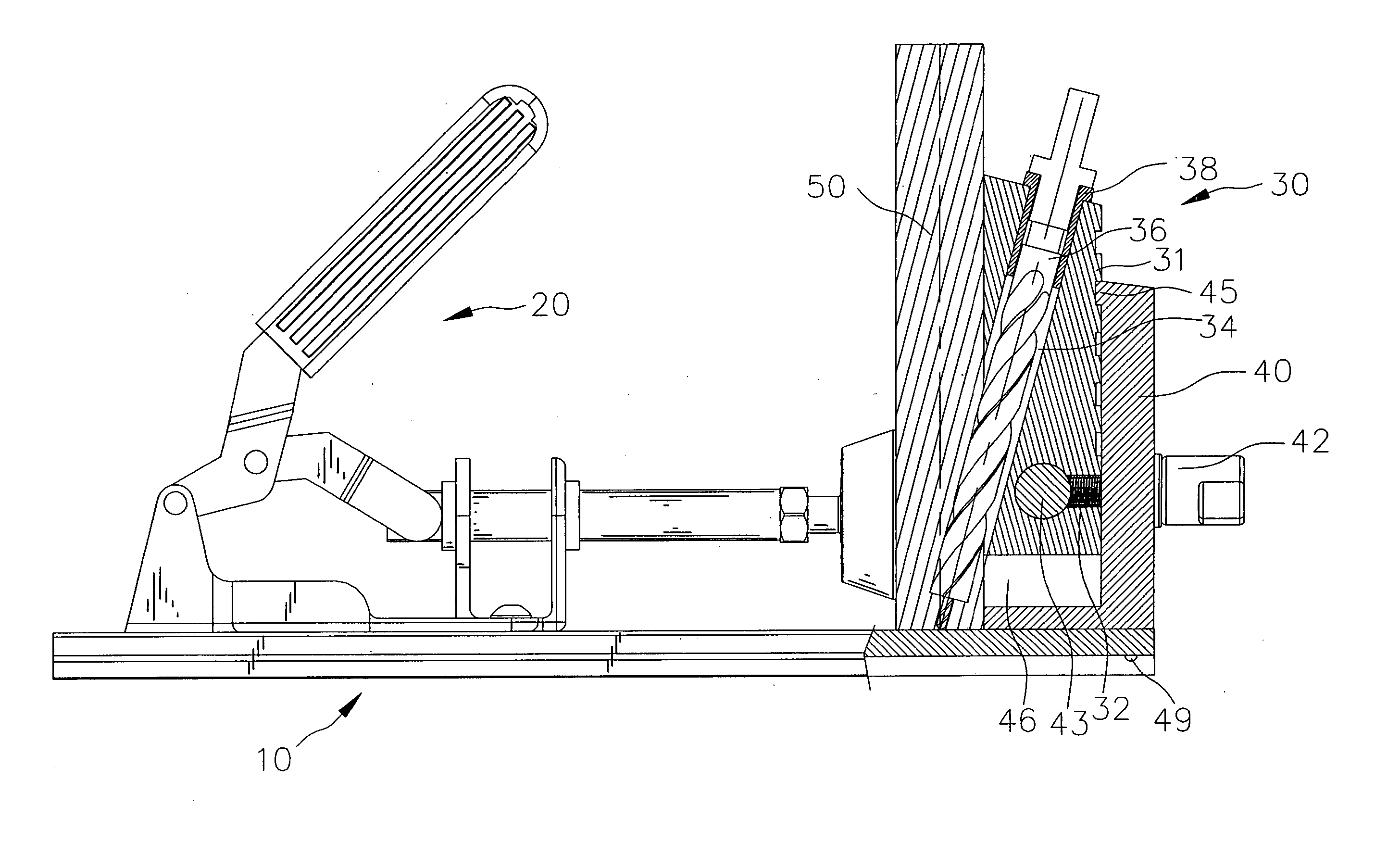
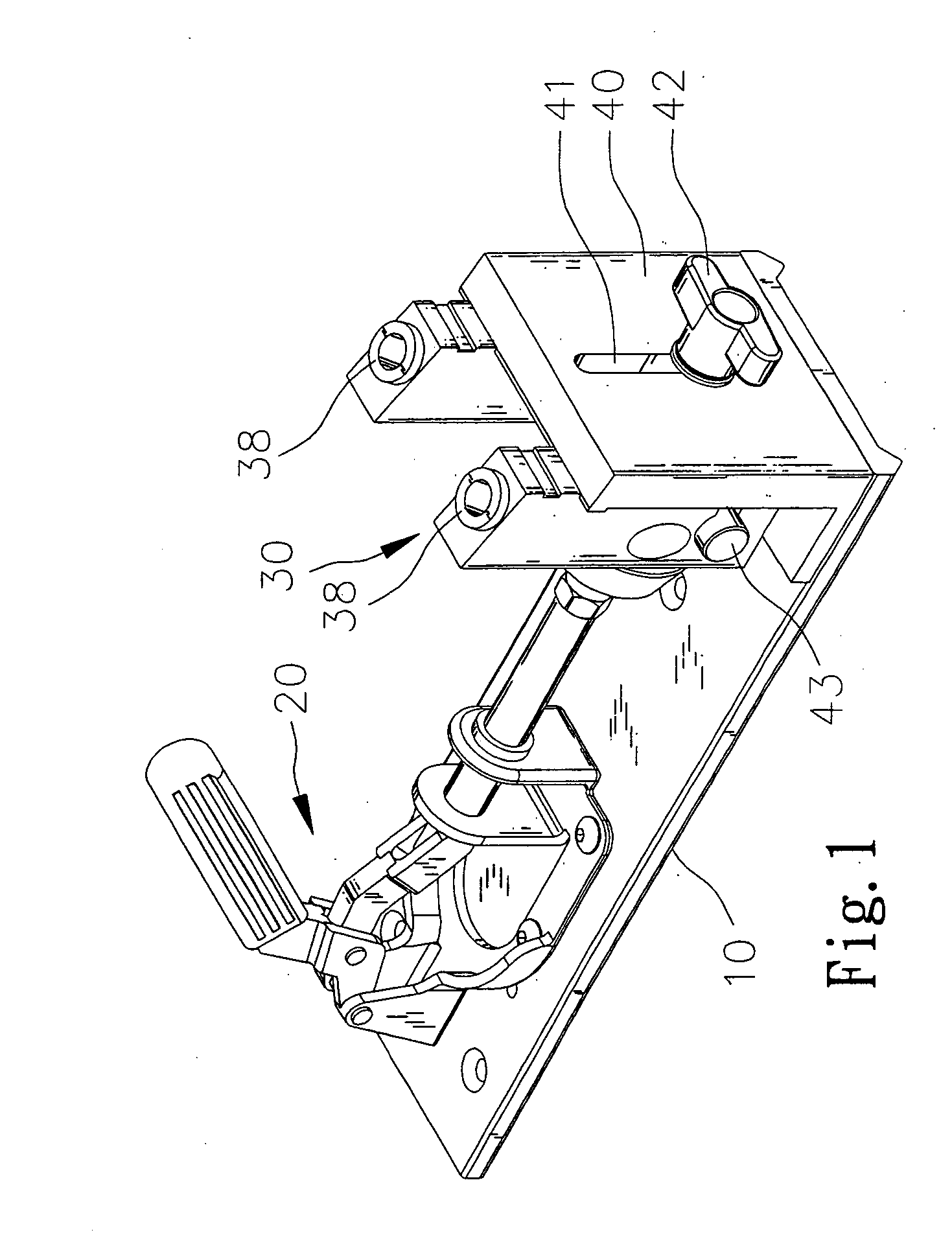
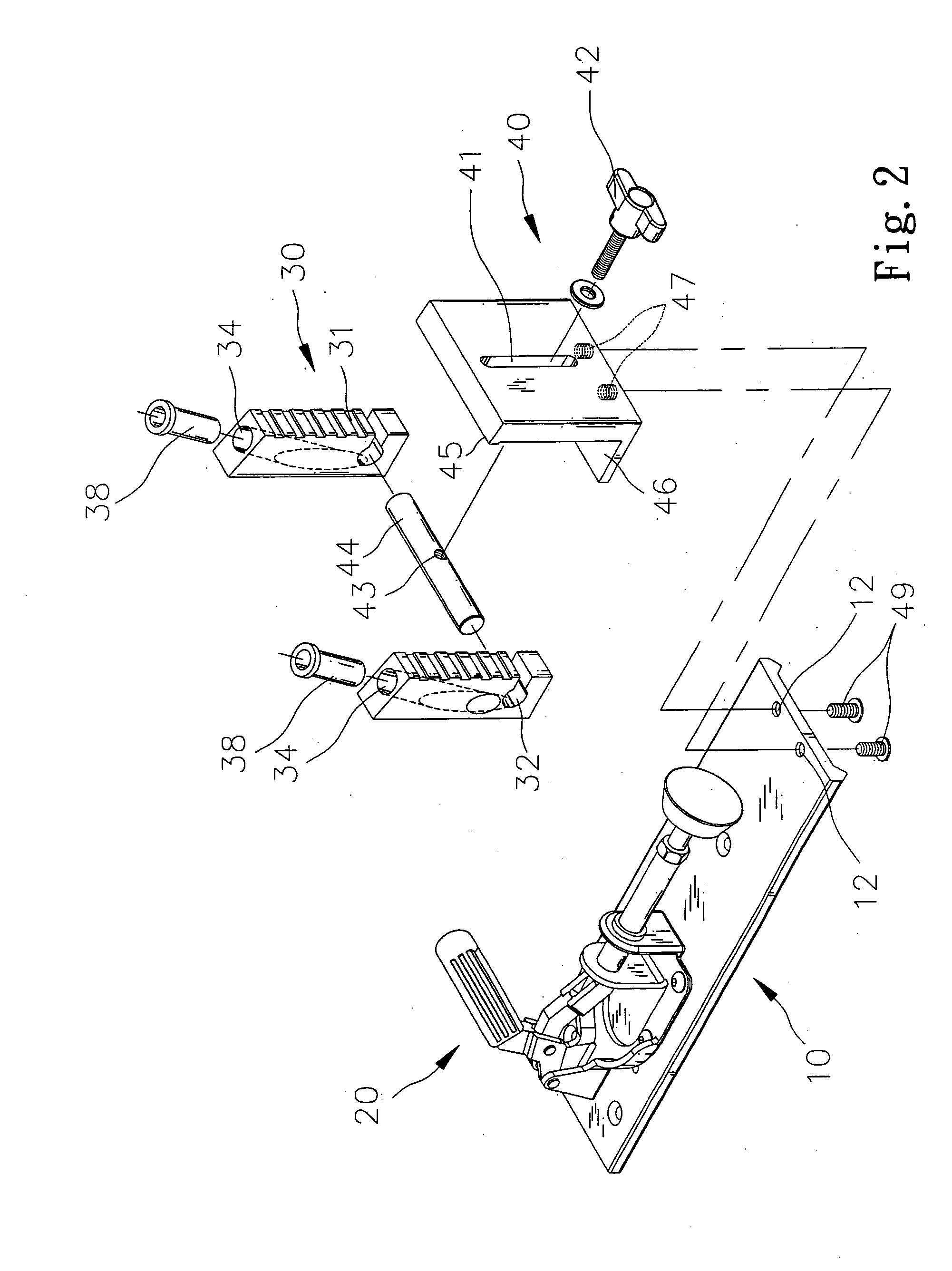
[0022] Referring to FIGS. 1 to 7, according to the present invention, a wood-drilling apparatus includes a table 10, a jig 20 attached to the table 10, a wall 40 attached to the table 10 and two cylinders 30 mounted on the wall 40.

[0023] The base 10 defines two apertures 12. The table 10 and the jib 20 will not be described in detail for being conventional. However, the wall 40 and the cylinders 30 will be described in detail.

[0024] Each of the cylinders 30 includes several ribs 31 formed thereon. Each of the cylinders 30 defines a hole 32 and an inclined passageway 34 for receiving a drill 36.

[0025] A rod 43 defines a screw hole 44. The rod 43 is inserted in the holes 32.

[0026] Thus, the cylinders 30 are smoothly movable along the rod 43.

[0027] The wall 40 includes a vertical slot 41 defined therein, a rib 45 formed thereon, a base 46 extending from a lower portion thereof and two screw holes 47 defined in the base 46.

[0028] Two screws 49 are driven into the screw holes 47 thr...

second embodiment

[0034] FIGS. 8 to 10 show a wood-drilling apparatus according to the present invention. The second embodiment is identical to the first embodiment except for including a face clamp 60 instead of the table 10 and the jig 20. The face clamp 60 includes a first jaw 62 and a second jaw 64. In use, the first jaw 62 is put against the wall 40, and the second jaw 64 the wooden workpiece 50. The wall 40 defines a recess 48 for receiving the first jaw 62.


PUM

PropertyMeasurementUnit
distanceaaaaaaaaaa
thicknessaaaaaaaaaa

Abstract

A wood-drilling apparatus includes a table, a wall, at least one cylinder, a jig and at least one drill. The wall is installed on the table. The cylinder is vertically movably mounted on the wall. The cylinder defines an inclined passageway. The jig is installed on the table for pushing a workpiece against the cylinder. The drill is movably inserted in the inclined passageway for drilling the workpiece.

Description

FIELD OF INVENTION [0001] The present invention relates to a wood-drilling apparatus. BACKGROUND OF INVENTION [0002]FIG. 11 shows a first conventional wood-drilling apparatus including a table 1, a wall 6 extending from the table 1, a jig 2 attached to the table 1 and two cylinders 3 put movably on the wall 6. Each of the cylinders 3 is retained in position relative to the wall 6 by means of a screw 4. Each of the cylinders 3 includes an inclined passageway 5 defined therein for receiving a drill. A wooden workpiece includes a front face, a rear face, a bottom and a top. The distance measured from the front face to the rear face will be referred to as “thickness” hereinafter. The wooden workpiece is put between the jig 2 and the cylinders 3. The front face is put against the cylinders 3, and the bottom the table 1. The drills are driven into the wooden workpiece, from the front face to the bottom. Thus, two holes are drilled in the wooden workpiece. Each hole includes a first open e...

Claims


Application Information

Patent Timeline
Patent Type & Authority Applications(United States)
IPC IPC(8): B23B47/28B23B49/02
CPCY10T408/567B23B47/287
Inventor LIU, HSU HSIU-KWEICHIU, MING-HSIANG
Owner LIU HSU HSIU KWEI
Why Eureka
Try Eureka