Spinal fixation system

a fixation system and spine technology, applied in the field of instruments, can solve problems such as disc degeneration, back pain, back pain,

a fixation system and spine technology, applied in the field of instruments, can solve problems such as disc degeneration, back pain, back pain,

US20050277923A1Active Publication Date: 2005-12-15ST CLOUD CAPITAL PARTNERS III SBIC LP

Image

  • Spinal fixation system
  • Spinal fixation system
  • Spinal fixation system

Examples


Embodiment Construction

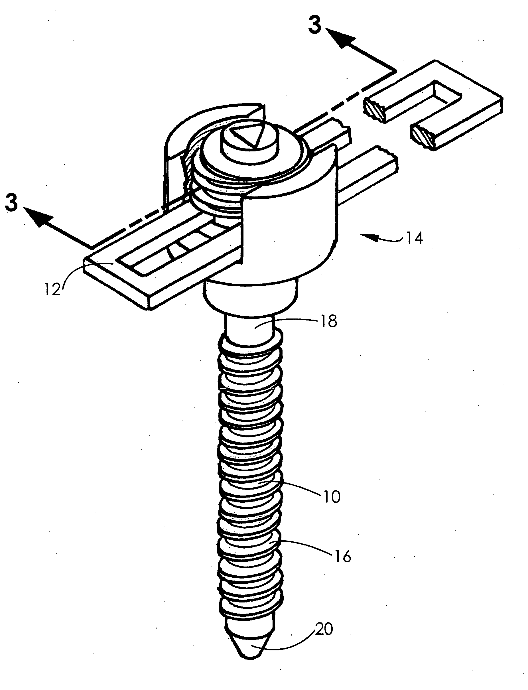
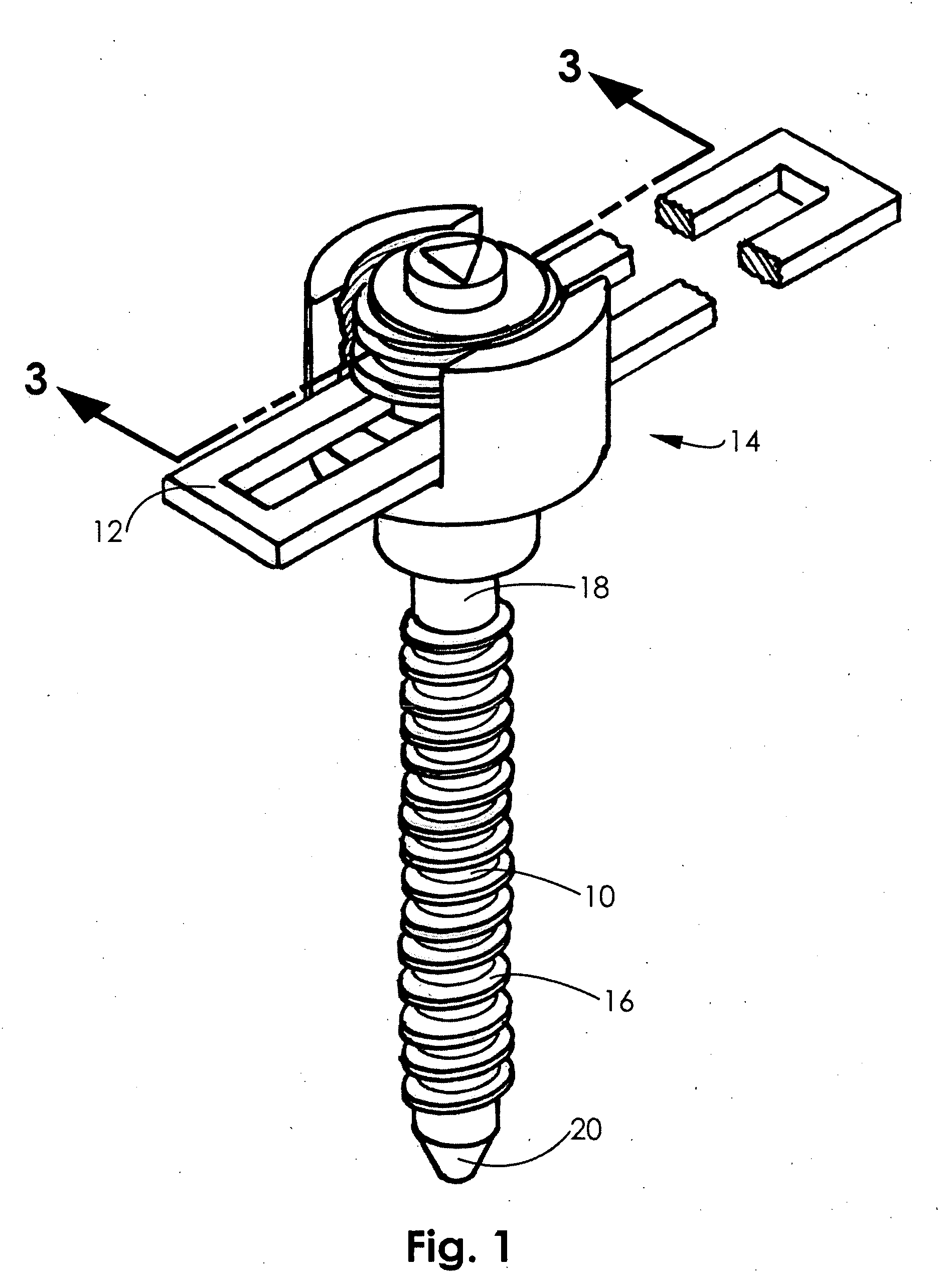
[0047] Referring to FIG. 1, in an exemplary embodiment of the invention, a spinal fixation system includes a bone anchoring element or bone screw, shown as pedicle screw 10. The pedicle screw 10 is coupled to a fixation element or linking device, shown as fixation plate 12, via a coupling mechanism 14. In use, the pedicle screw 10 may be inserted through a pedicle and into a vertebra and linked to other pedicle screws by the fixation plate 12. The length of the fixation plate 12 is chosen to accommodate the total distance between the pedicle screws that are linked together.

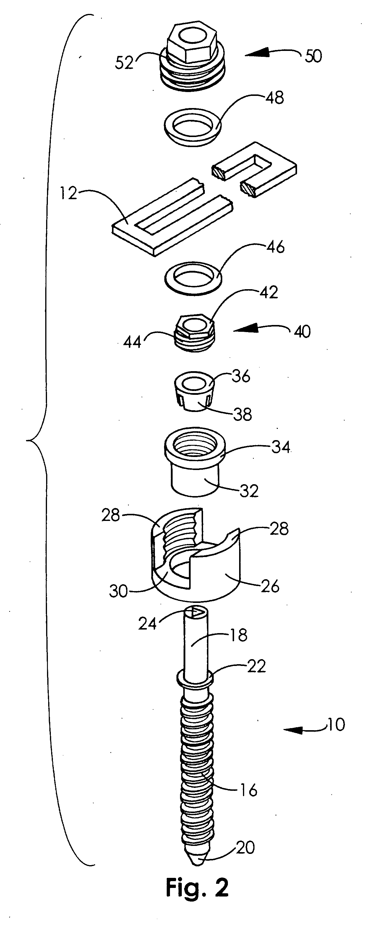
[0048] Referring to FIG. 2, the pedicle screw 10 includes a threaded portion 16 and a non-threaded upper portion, shown as post 18. A tip 20 may be configured to be self-drilling and a shoulder or flange 22 may extend from the screw 10 between the post 18 and threaded portion 16. At the top of the post 18, an engagement mechanism for a screwdriver or drill, shown as recess 24, may be utilized. A receiver 26 inclu...


PUM


Abstract

A spinal fixation system includes a pedicle screw having a passage extending along a longitudinal axis of the screw. The passage has a proximal opening at a proximal end of the screw and a distal opening at a distal end of the screw. A drill extends through the passage, a first end of the drill extending out the distal opening of the passage.

Description

FIELD OF THE INVENTION [0001] The present invention relates to instrumentation and methods used in the performance of spinal fusion procedures. In particular, the present invention relates to a spinal fixation system and related surgical methods. BACKGROUND OF THE INVENTION [0002] The spinal column is comprised of twenty-six interlocking vertebrae. These vertebrae are separated by disks. The spine provides load-bearing support for one-half of the body's mass and it protects the nerves of the spinal column. The disks provide shock absorption and facilitate the bending of the spine. [0003] The combination of the vertebrae and disks at each vertebral segment allows for motion of the spine, in particular, flexing, rotation, and extension. The motion and support functions of the spine, in combination with the many interlocking parts and nerve roots associated with the spinal column can result in back pain due to various reasons. Such back pain may result from the degeneration of disks du...

Claims


Application Information

Patent Timeline
15 Dec 2005
Publication
US20050277923A1
IPC
A61B17/00; A61B17/16; A61B17/70; A61B17/86; A61F2/30; A61F2/44
CPC
A61B17/1671; A61B17/7005; A61B17/7007; A61F2/4455; A61B17/7032; A61B17/7041; A61B17/864; A61B17/701
Inventors
SWEENEY, PATRICK J.