Eureka AIR delivers breakthrough ideas for toughest innovation challenges, trusted by R&D personnel around the world.

Crimpable intraluminal endoprosthesis having helical elements

Inactive Publication Date: 2005-04-28
ORBUSNEICH MEDICAL PTE LTD
View PDF6 Cites 23 Cited by
  • Summary
  • Abstract
  • Description
  • Claims
  • Application Information

AI Technical Summary

Benefits of technology

[0008] The present invention is directed to expandable stents that have geometries that allow them to be readily crimped onto a balloon delivery device. In one embodiment, the stent may be comprised of a plurality of first helical segment having a first helical angle with respect to the longitudinal axis of the stent and a plurality of second helical segments that have a second helical angl

Problems solved by technology

These include, but are not limited to: (i) low stent-to-vessel ratio uniformity, (ii) comparative rigidity of the stent in a crimped as well as deployed state, and (iii) limited flexibility making delivery and placement in narrow vessels difficult.

Method used


Image

  • Crimpable intraluminal endoprosthesis having helical elements
  • Crimpable intraluminal endoprosthesis having helical elements
  • Crimpable intraluminal endoprosthesis having helical elements

Examples


Embodiment Construction

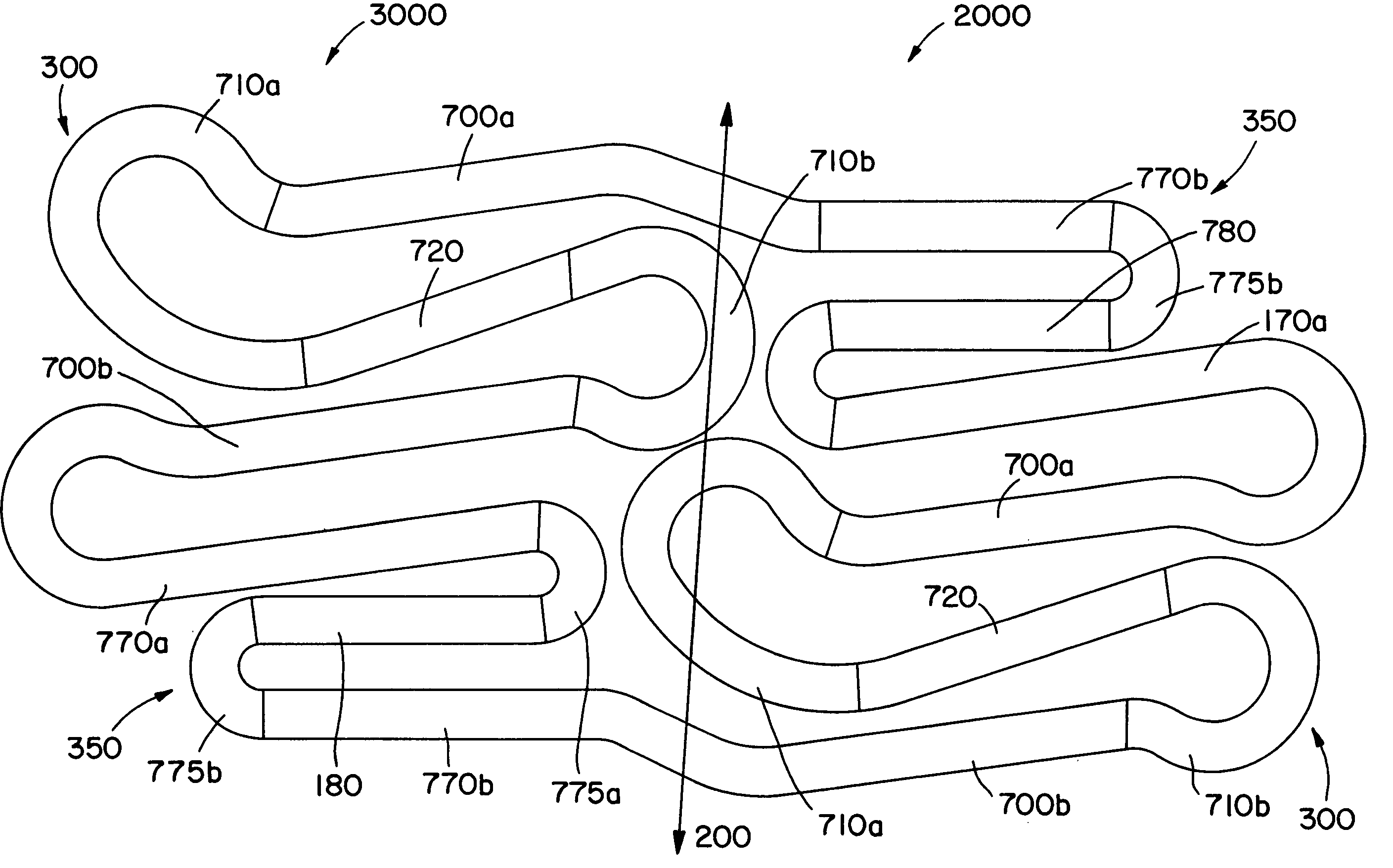
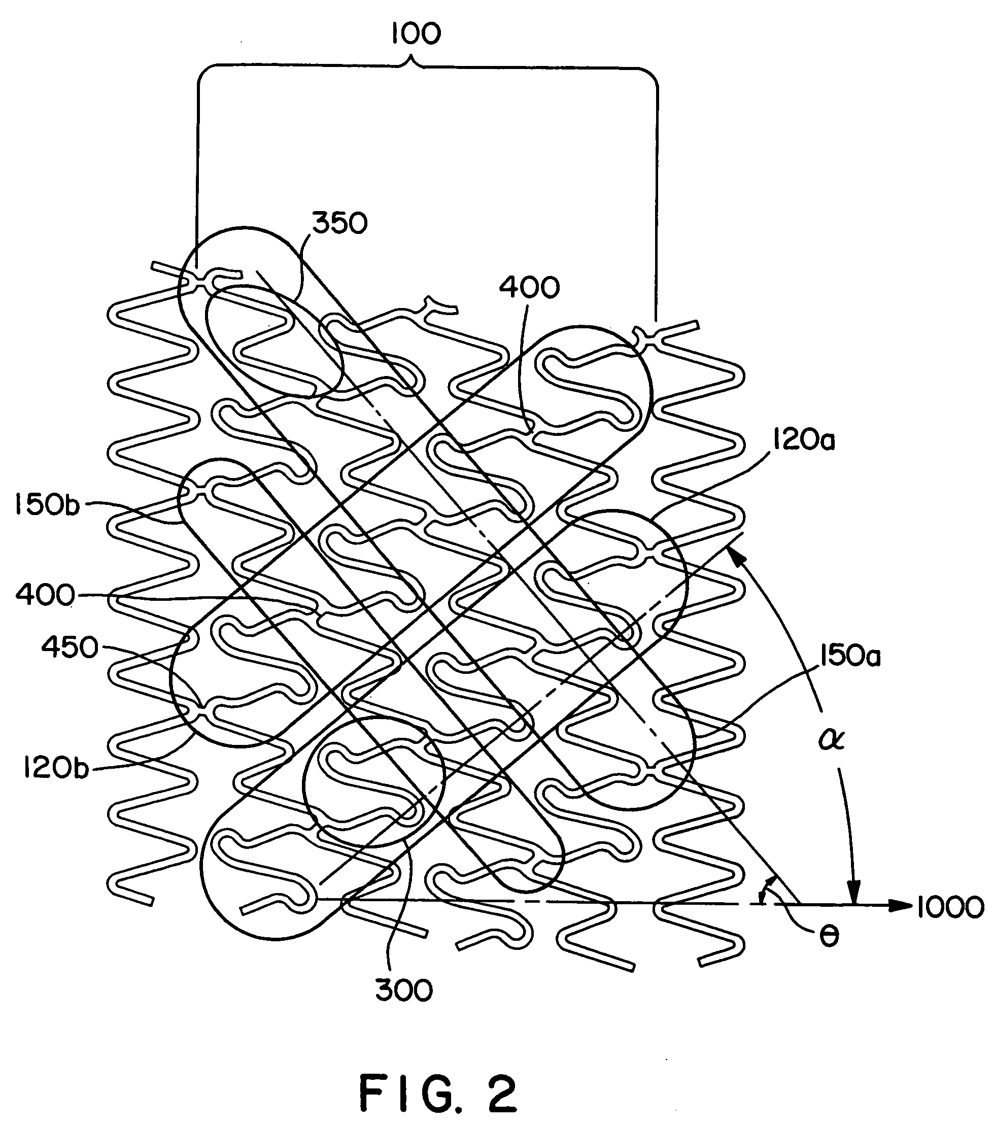
[0022] The present invention is directed to an expandable stent having a geometry that is well-suited for crimping the stent onto a delivery device. In some, but not necessarily all embodiments of the present invention, the stents may have an expanded diameter that is 3 to 6 times that of its crimped diameter. In addition, in some—but not necessarily all—embodiments the stent-to-vessel ratios may be better than 15%.

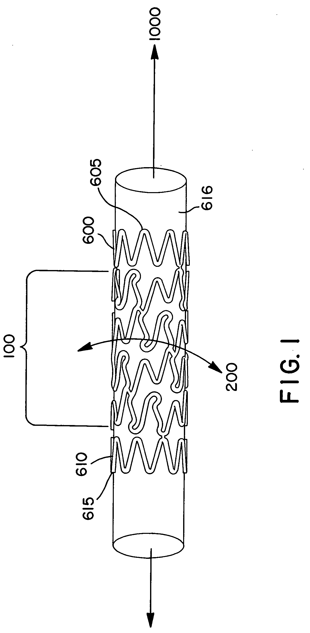
[0023] In one embodiment of the present invention, as is shown in FIGS. 1 & 2, a stent is comprised of a main body section 100 having a longitudinal axis 1000. The stent shown in FIG. 1 is mounted on a carrier 616. The main body is comprised of a plurality of first helical segments 120a and 120b and a plurality of second helical segments 150a and 150b. The first helical segments form a helical angle α with respect to the longitudinal axis 1000 of the stent, resulting in the first helical segments having a first pitch. The second helical segments 150a and 150b form a heli...


PUM


Abstract

A stent having helical elements, a geometry for improved crimping, and a good stent-to-vessel ratio is disclosed. In one embodiment, the stent has a plurality of first helical segments and a plurality of second opposing helical segments. The first helical segments are comprised of a plurality of first expandable elements and the second helical segments are comprised of a plurality of second helical elements. The expandable elements are joined to each other by a plurality of struts. When the stent is crimped a portion of one of the first expandable elements nest within another portion of the same expandable element and a portion of two first expandable elements nestle between the same two portions of second expandable elements.

Description

[0001] This application claims the benefit of U.S. Provisional Application No. 60 / 267,778, filed on Feb. 9, 2001, which is hereby incorporated in its entirety by reference, and it is a continuation-in-part of U.S. patent application Ser. No. 09 / 511,481, filed on Feb. 23, 2000, which is also hereby incorporated in its entirety by reference and which is a continuation of U.S. patent application Ser. No. 09 / 094,402, filed Jun. 10, 1998 (now U.S. Pat. No. 6,117,165).BACKGROUND OF THE INVENTION [0002] 1. Field of the Invention [0003] The present invention relates to intraluminal endoprosthetic devices known as stents. In particular, the present invention relates to stents having helical elements with a geometry that allows the stent to be readily crimped onto a delivery device. [0004] 2. Description of Related Art [0005] Stents are prosthetic devices that are implanted in the lumen of a vessel inside the body to provide support for the vessel's wall. Structural support from stents is par...

Claims


Application Information

Patent Timeline
IPC IPC(8): A61F2/84A61F2/90
CPCA61F2/88A61F2/91A61F2/915A61F2002/91508A61F2002/91516A61F2230/0013A61F2002/91533A61F2002/91541A61F2002/9155A61F2002/91558A61F2002/91583A61F2002/91525
Inventor PAZIENZA, JOHN D.PIFERI, PETER G.BECKER, GARY J.
Owner ORBUSNEICH MEDICAL PTE LTD
Why Eureka
Eureka Blog
Learn More