Pneumatic tire

a technology of pneumatic tires and tires, applied in the field of pneumatic tires, can solve the problems of deteriorating traction performance at the wear end stage, affecting the performance of pneumatic tires, etc., and achieves the effect of improving traction performance and drainage performance, and improving traction performan

Active Publication Date: 2005-05-05
TOYO TIRE & RUBBER CO LTD
View PDF4 Cites 29 Cited by
  • Summary
  • Abstract
  • Description
  • Claims
  • Application Information

AI Technical Summary

Benefits of technology

[0012] The preferred embodiments of the present invention have been developed in view of the above-mentioned and / or other problems in the related art. The preferred embodiments of the present invention can significantly improve upon existing methods and / or apparatuses.

Problems solved by technology

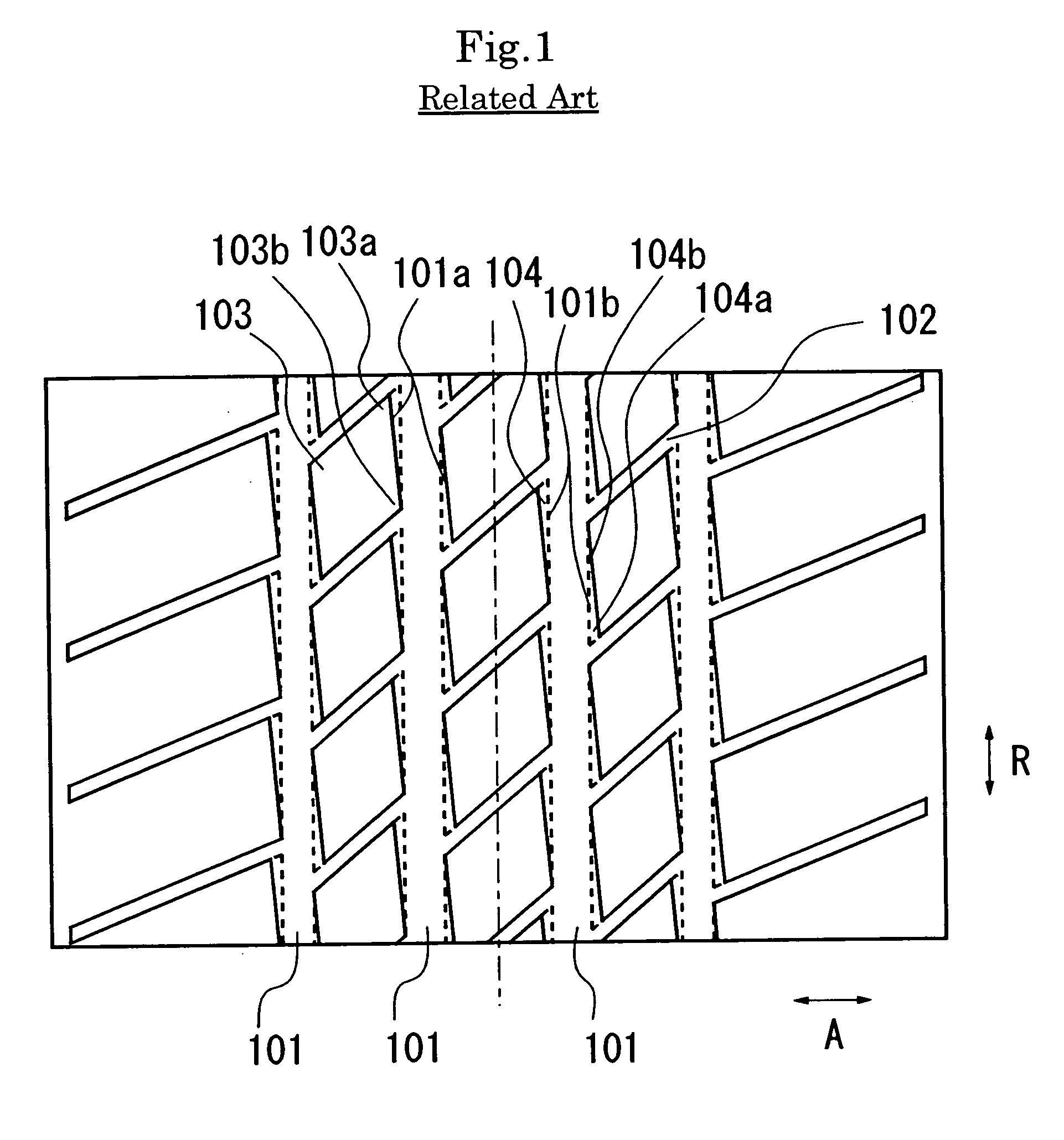
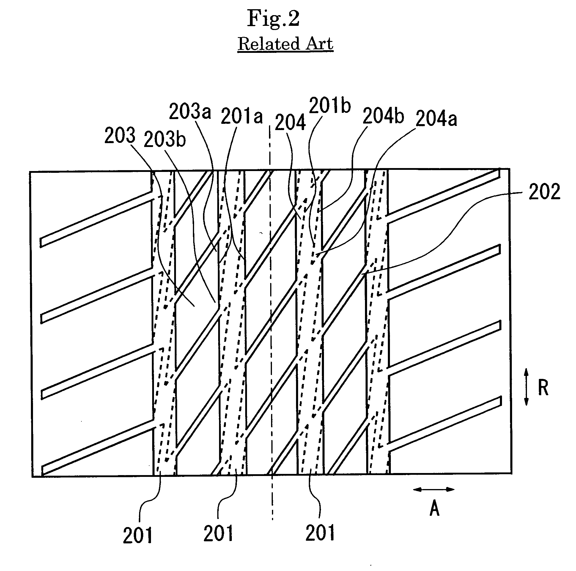
In pneumatic tires having substantial parallelogram block patterns, the block is smaller in rigidity at the acute corner portion than at the obtuse corner portion, causing irregular wear.
As a result, the traction performance deteriorates at the wear end stage.
As described above, it has been difficult to keep both the good traction performance and the good drainage performance at the same time at the wear end stage.

Method used


Image

  • Pneumatic tire
  • Pneumatic tire
  • Pneumatic tire

Examples


example

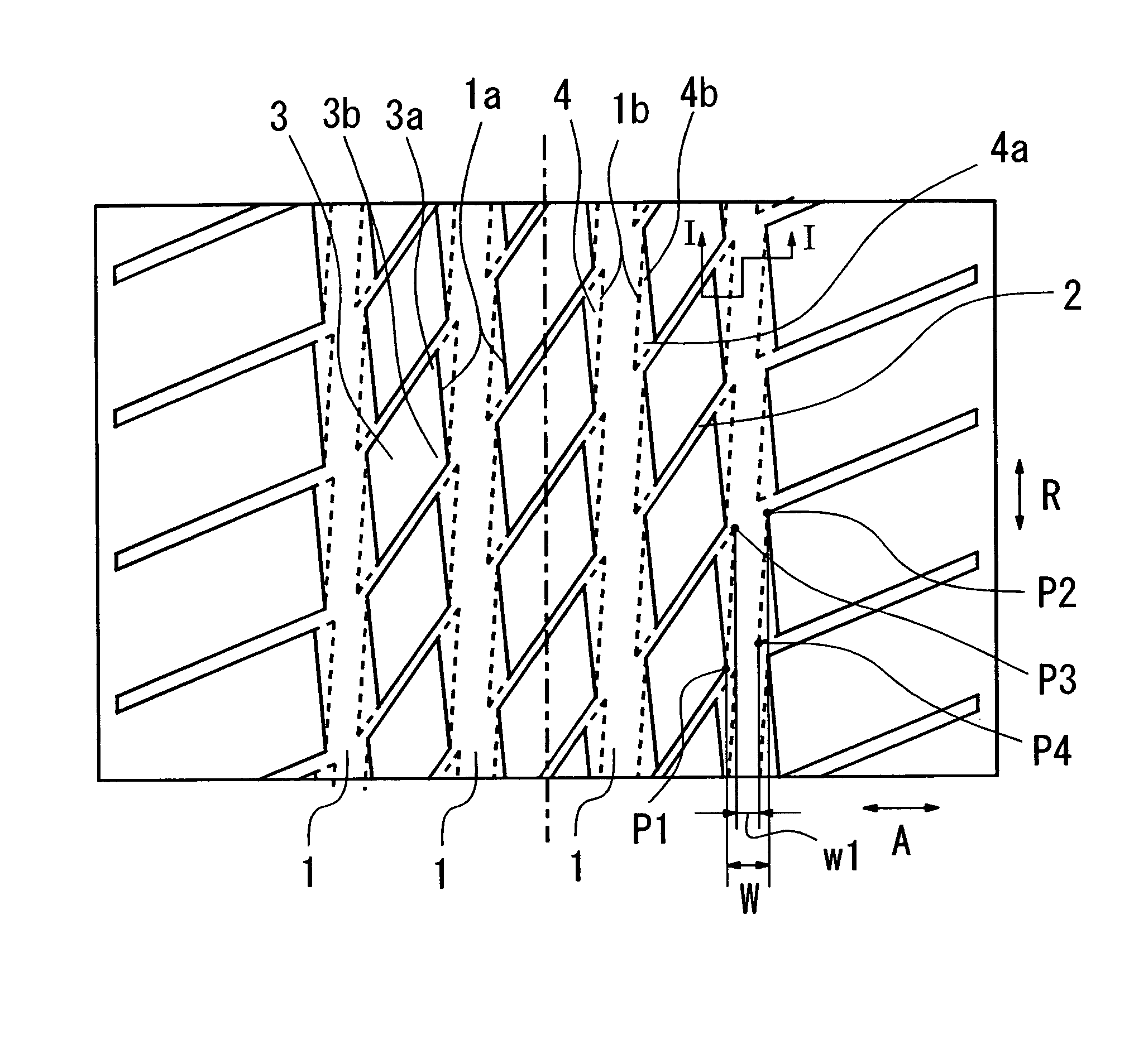
[0042] As an Example, a pneumatic tire according to the present invention was prepared. On the other hand, as Comparative Examples 1 and 2, pneumatic tires in which an extending direction of the main groove at the tread surface level and the extending direction of the main groove at the groove bottom level are not opposite were prepared. Then, these tires were applied to a four-wheel-drive domestic car of 2000 cc to evaluate each performance. The pattern of Example is shown in FIG. 6 and the patterns of Comparative Examples 1 and 2 are shown in FIGS. 7 and 8. In all of these tires, the inclination angles of the groove sides at the outermost main grooves were changed. In these tires, the maximum value of the inclination angle al of the groove side 4a at the side of the block acute corner portion 3a was 30° and the minimum value of the inclination a2 of the groove side 4b at the side of the block obtuse corner portion 3b was 0°. The tire size was 225 / 70R16 and the air pressure was 210...


PUM


Abstract

A pneumatic tire includes main grooves 1 extending substantially in a circumferential direction R of the tire, transverse grooves 2 connecting adjacent main grooves, and blocks 3 formed by adjacent main grooves and adjacent transverse grooves. Each block 3 has an acute corner portion 3a and an obtuse corner portion 3b and also has a groove side extending along the main groove 1 between the acute corner portion 3a and the obtuse corner portion 3b. An inclination angle a1 of the groove side increases from the obtuse corner portion 3b toward the acute corner portion 3a. An extending direction 1a of the main groove 1 at a tread surface level is inclined toward one side of the main groove 1 with respect to the circumferential direction R of the tire, while an extending direction of the main groove 1 at a groove bottom level is inclined toward the other side.

Description

[0001] This application claims priority under 35 U.S.C. § 119 to Japanese Patent Application No. P2003-370987 filed on Oct. 30, 2003, the entire disclosure of which is incorporated herein by reference in its entirety. BACKGROUND OF THE INVENTION [0002] 1. Field of the Invention [0003] This invention relates to a pneumatic tire having substantial parallelogram block patterns. More specifically, it relates to a pneumatic tire capable of preventing irregular wear at the wear early stage and obtaining sufficient drainage and traction performance at the wear end stage. [0004] 2. Description of the Background [0005] The following description sets forth the inventor's knowledge and should not be construed as an admission that the description constitutes prior art. [0006] In pneumatic tires having substantial parallelogram block patterns, the block is smaller in rigidity at the acute corner portion than at the obtuse corner portion, causing irregular wear. [0007] In order to prevent such ir...

Claims


Application Information

Patent Timeline
Patent Type & Authority Applications(United States)
IPC IPC(8): B60C11/04B60C11/13B60C11/11
CPCB60C11/13Y10S152/902Y10S152/90
Inventor MIYAZAKI, TETSUJI
Owner TOYO TIRE & RUBBER CO LTD
Why Eureka
Try Eureka