Method for forming a heat exchanger stack

a technology of heat exchangers and stacks, applied in the field of heat exchangers, to achieve the effect of resisting electromagnetic impulse welding

Inactive Publication Date: 2005-05-05
SEIDEL PESSACH
View PDF0 Cites 15 Cited by
  • Summary
  • Abstract
  • Description
  • Claims
  • Application Information

AI Technical Summary

Benefits of technology

[0018] In accordance with a further embodiment of the present invention, a substrate of a non-conductive material is selectively applied to one surface of the edge portions and to the generally flat central portion of one or more of the two or more nestable plates, thereby to provide resistance to electromagnetic impulse welding thereto.

Problems solved by technology

There arises a problem in regard to the above prior art embodiment, however, in so far as severe distortion is found to occur to plates 60 and 70.

Method used


Image

  • Method for forming a heat exchanger stack
  • Method for forming a heat exchanger stack
  • Method for forming a heat exchanger stack

Examples


Embodiment Construction

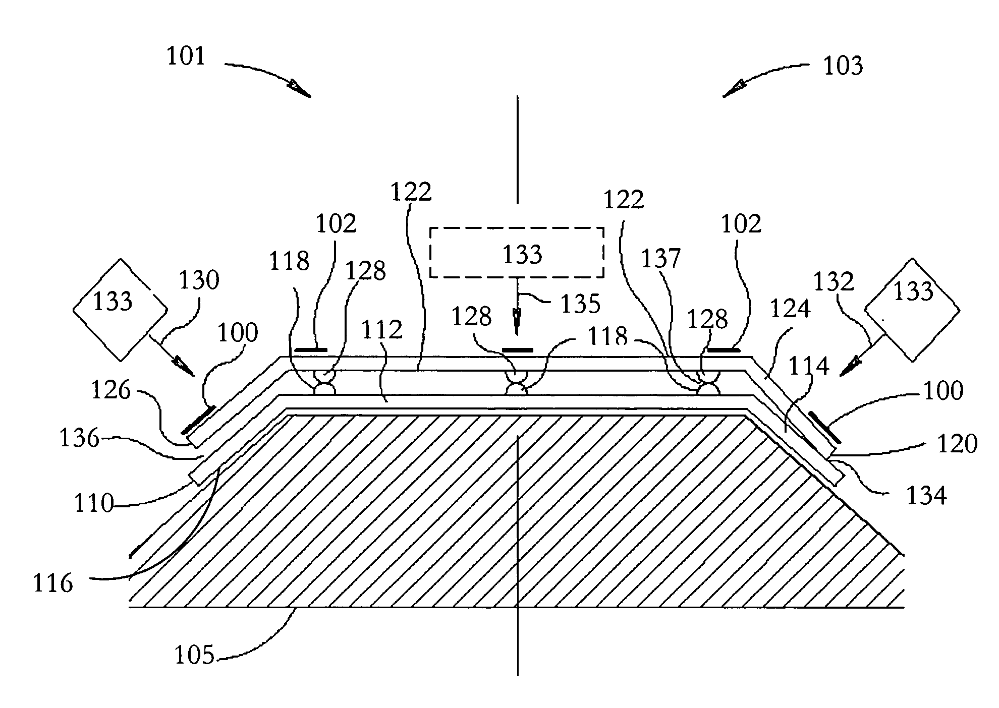
[0048] The present invention discloses a means for facilitating electromagnetic impulse welding of a stack of heat exchanger plates together wherein the heat exchanger plates are formed from less conductive or even non-conductive materials which are substantially unresponsive to electromagnetic impulse welding, while reducing or preventing distortion of the plates.

[0049] Referring now to FIG. 5, there is illustrated an application in accordance with a preferred embodiment of the present invention. On the left side generally referenced 101 of FIG. 5, there is shown the disposition onto base 105 of lower plate 110 and upper plate 120 before welding and on the right, generally referenced 103, after welding. Prior to welding, there is an acceleration gap provided between opposing protrusions referenced 118 and 128. In addition, as an improvement to what is disclosed in the prior art U.S. Pat. No. 6,513,240, facilitating substrates referenced 100, which are substantially more responsive...


PUM

PropertyMeasurementUnit
resistanceaaaaaaaaaa
electromagnetic impulse energyaaaaaaaaaa
kinetic forceaaaaaaaaaa

Abstract

A heat exchanger stack includes two or more nestable plates formed of a plate material being substantially unresponsive to electromagnetic impulse welding, and wherein each plate includes a generally flat central portion having a plurality of protrusions protruding from one or more surfaces thereof and one or more pairs of edge portions generally formed non-coplanar relative to the generally flat central portion. The two or more plates are arranged in a nesting arrangement and spaced apart by the protrusions so as to define therebetween a space through which a heat exchange medium may flow. Further, two or more plates are affixed together by electromagnetic pulse welds at a plurality of welding locations which include the protrusions and one or more pairs of edge portions. Also, the two or more plates are mutually connected at the welding locations via a facilitator substrate, which is highly responsive to electromagnetic impulse welding, and which is disposed on one or more of the two plates.

Description

FIELD OF THE INVENTION [0001] The present invention relates, generally to heat exchangers and, more specifically, to forming a stack of heat exchanger plates. GLOSSARY Facilitating Substrate [0002] An applied coating, layer or covering of material substantially responsive to applied electromagnetic impulse energy for application to a surface of an object substantially unresponsive to electromagnetic impulse energy, thereby to effectively provide the object with substantial responsiveness to electromagnetic impulse energy. BACKGROUND OF THE INVENTION [0003] It is known in the art to provide for forming a stack of heat exchanger plates which are welded together using a high energy, short duration electro-magnetic pulse. [0004] With reference to U.S. Pat. No. 6,513,240 dated Feb. 4, 2003 entitled “Method of forming a heat exchanger stack” to Pessach Seidel, who is also the inventor of the present invention, there is described a method for forming a heat exchanger stack from a plurality...

Claims


Application Information

Patent Timeline
Patent Type & Authority Applications(United States)
IPC IPC(8): B23K31/12F28D9/00F28F3/08
CPCB23K31/12F28F3/08F28D9/0037B23K2201/14B23K2101/14
Inventor SEIDEL, PESSACH
Owner SEIDEL PESSACH
Why Eureka
Try Eureka