Supporting plate, stage device, exposure apparatus, and exposure method

a stage device and support plate technology, applied in the field of supporting plates, can solve problems such as device/member failure, rust/oxidation, and liquid on the wafer may increase and be splashed at the periphery, and achieve the effect of reducing the effects of problems and suppressing problems

Active Publication Date: 2005-05-05
NIKON CORP
View PDF26 Cites 433 Cited by
  • Summary
  • Abstract
  • Description
  • Claims
  • Application Information

AI Technical Summary

Benefits of technology

The present inventors have developed an improved method for controlling how much light falls on top surfaces during lithography processes used with photopolymerizable materials (photocurable resin). This helps prevent damage from particles that may get stuck inside these devices while they are being worked upon.

Problems solved by technology

The patent text discusses the use of a liquid crystal display device and a semiconductor device that are manufactured using a photolithographic method. The exposure apparatus used in this process is designed to transfer a pattern from a mask onto a substrate. To achieve higher resolution, the exposure wavelength has been shortened and the numerical aperture of the projection optical system has been increased. However, this also narrows the depth of focus, making it difficult to match the substrate surface with the image plane of the projection optical system. To address this issue, a liquid immersion method has been proposed, which uses liquid to improve resolution and increase the depth of focus. The technical problem of the patent text is how to improve the resolution and depth of focus in the photolithographic process while maintaining the efficiency of the exposure apparatus.

Method used


Image

  • Supporting plate, stage device, exposure apparatus, and exposure method
  • Supporting plate, stage device, exposure apparatus, and exposure method
  • Supporting plate, stage device, exposure apparatus, and exposure method

Examples


first embodiment

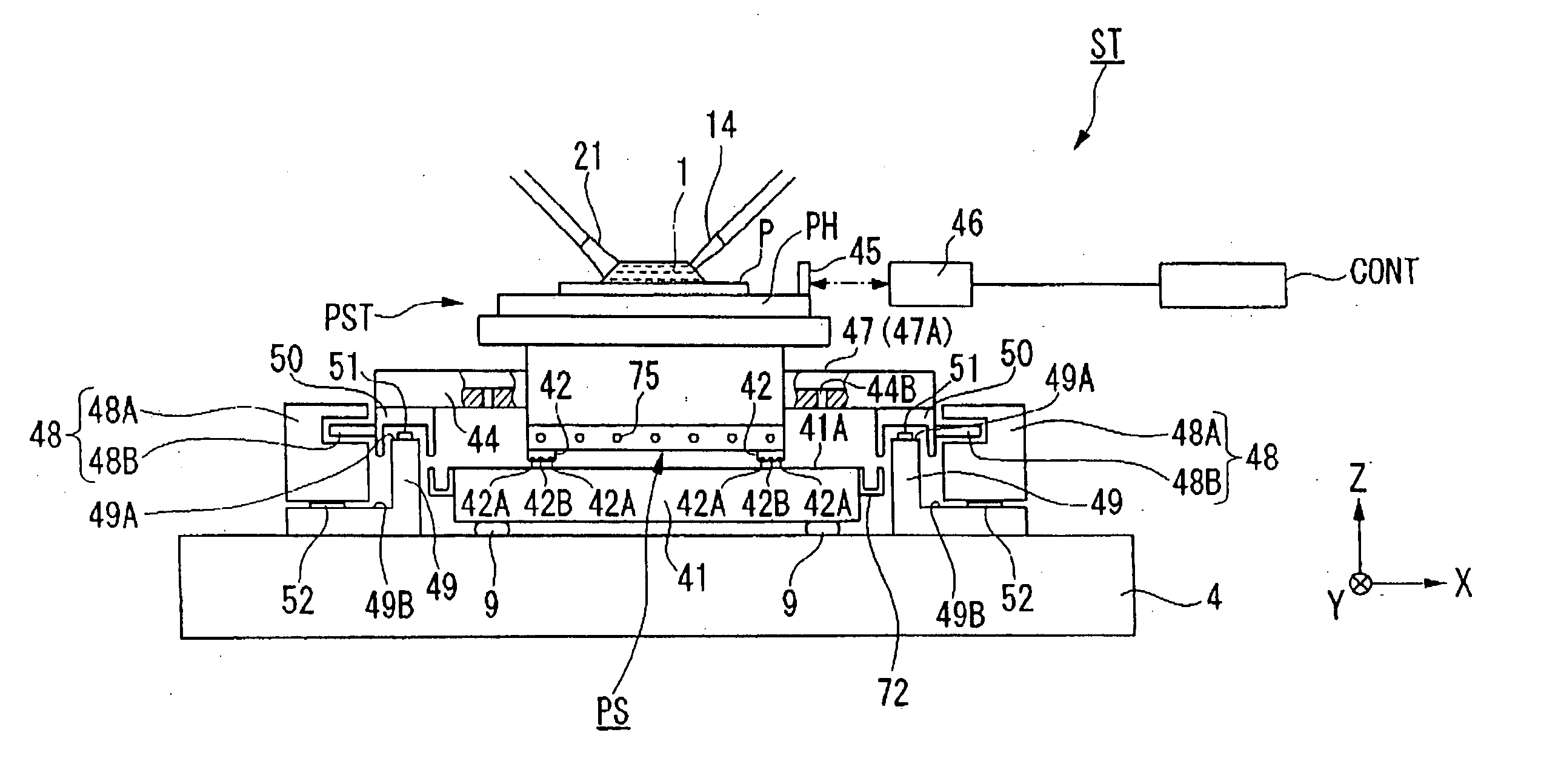
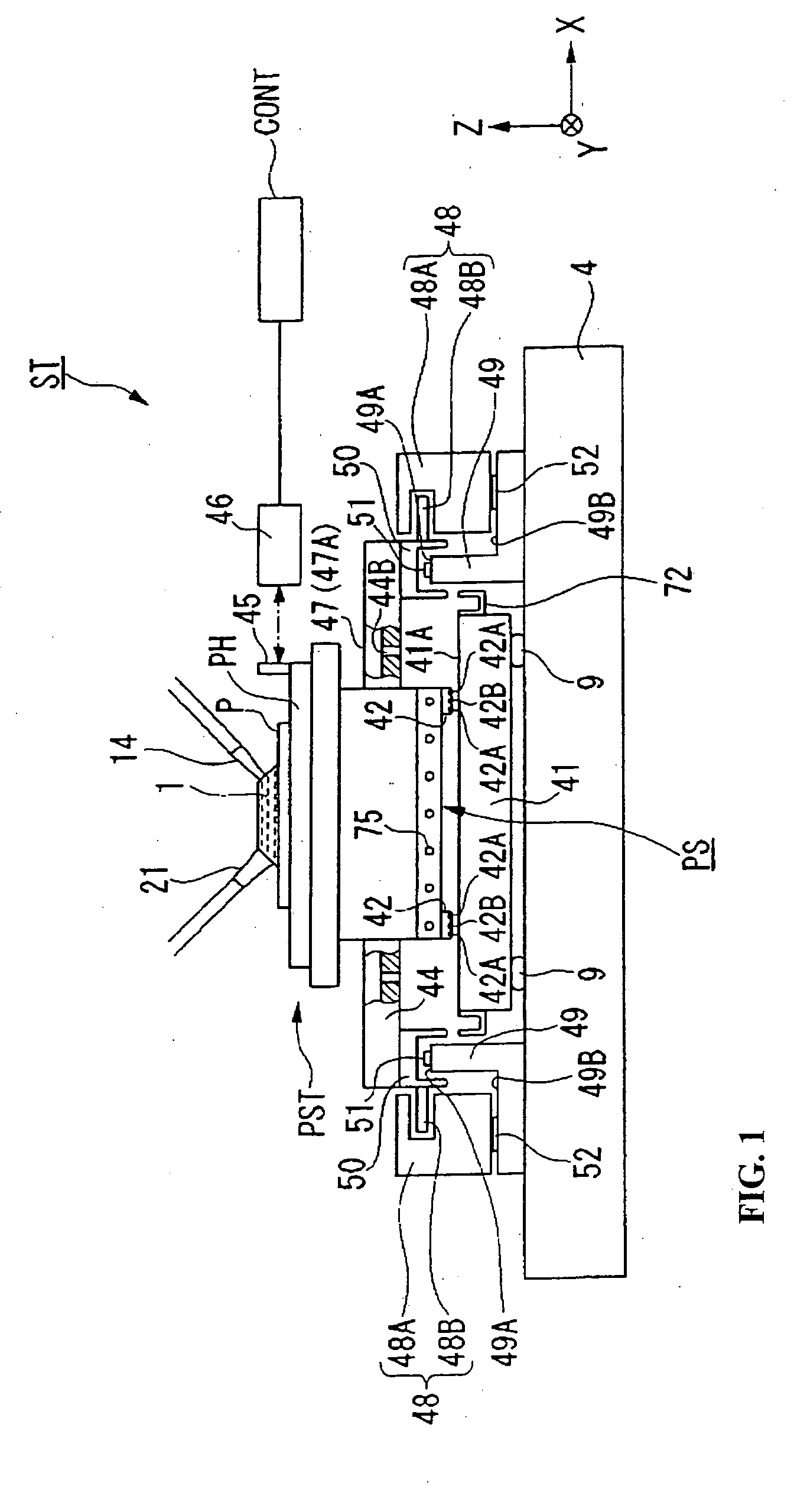
[0034] A first embodiment explains a supporting plate according to some aspects of this invention, and a stage device provided with this supporting plate. FIG. 1 is a schematic structural diagram showing an embodiment of a stage device utilizing some aspects of this invention.

[0035] A stage device ST shown in FIG. 1 is mainly constituted by a substrate supporting plate (supporting plate) 41 which is supported by three or four points on a base plate 4 via a vibration isolation unit (removal device) 9, a substrate stage PST as an object (movable body) which supports the substrate P and moves a top surface (support surface) 41A of the substrate supporting plate 41, an X linear motor 47 which drives the substrate stage PST in an X axis direction (horizontal direction in FIG. 1), and a Y linear motor 48 which drives the substrate stage PST in a Y axis direction (direction perpendicular to a paper plane of FIG. 1). The vibration isolation unit 9 is provided with an actuator such as an air...

second embodiment

[0059] Next, a supporting plate and stage device utilizing aspects of this invention is explained. FIG. 4 is a diagram schematically showing the substrate stage PST, the substrate supporting plate 41, and the X guide stage 44 within the stage device. Furthermore, in FIG. 4, the moving mirror and the substrate on the substrate stage PST, and the gutter of the substrate supporting plate 41 are omitted from the drawing, although they would be present in the actual device.

[0060] In this embodiment, as shown in FIG. 4, on the top surface of the table portion PH of the substrate stage PST, a groove portion 76 is formed along an edge (outer circumference). Furthermore, on one side surface of the table portion PH, a slot portion 77 is formed which is positioned above a concave portion 44C of the X guide stage 44, and extends in the Z axis direction, and is connected to the groove portion 76.

[0061] Furthermore, in the concave portion 44C of the X guide stage 44, a drain port 44B is formed a...


PUM


Abstract

For example, to control an effect due to entrance and leakage of liquid for exposure and allow a preferable exposure processing, a support surface is provided which supports an object. The support surface is liquid repellant, and a collection device is provided which collects liquid from the support surface.

Description


Claims


Application Information

Patent Timeline
Owner NIKON CORP
Why Eureka
Try Eureka