
Security document with an optical security area

a security area and security document technology, applied in the field of security documents, to achieve the effect of enhancing the recognizability of security signs

Inactive Publication Date: 2005-05-05
OESTERR BANKNOTEN UND SICHERHEITSDRUCK
View PDF2 Cites 18 Cited by
  • Summary
  • Abstract
  • Description
  • Claims
  • Application Information

AI Technical Summary

Benefits of technology

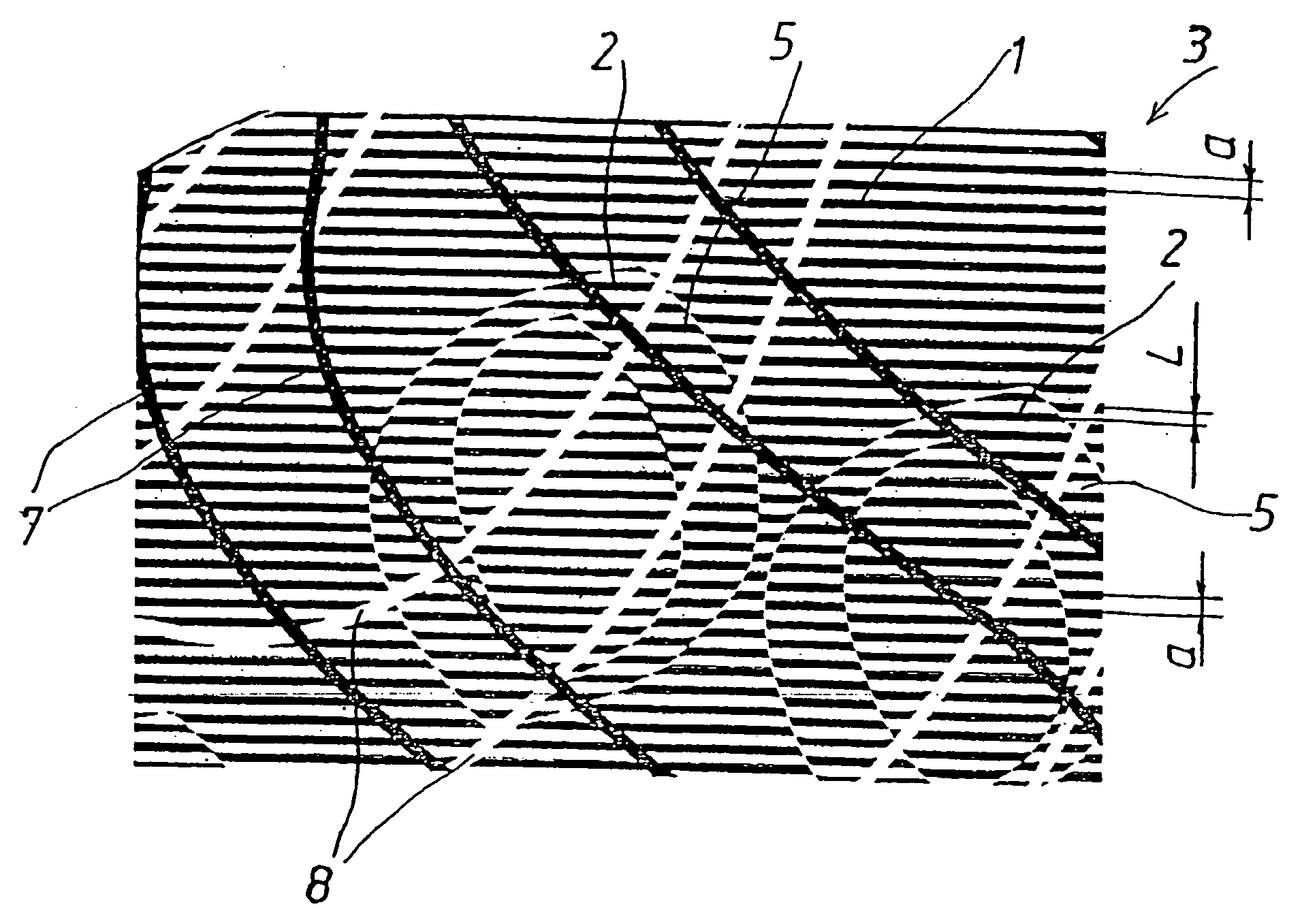
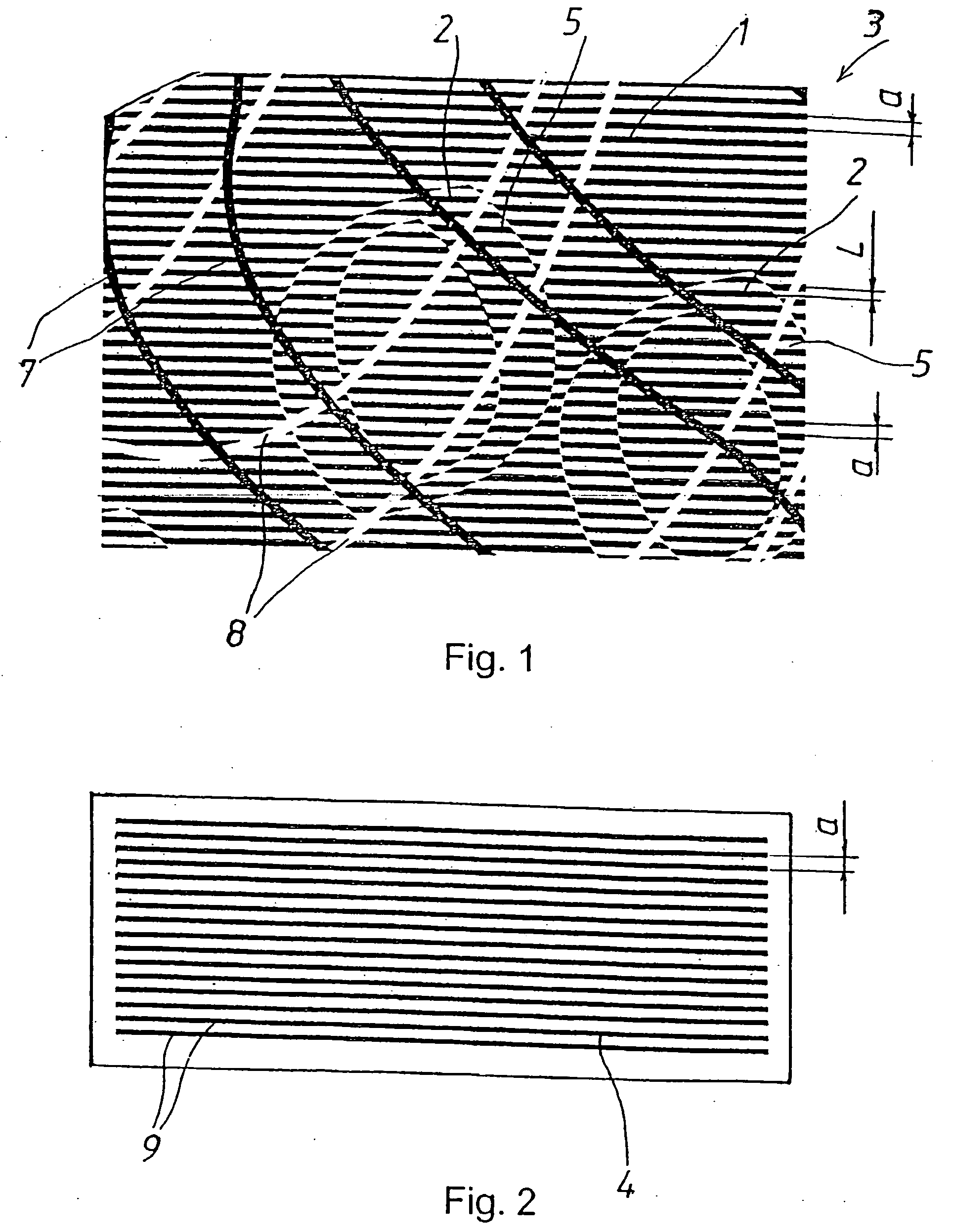
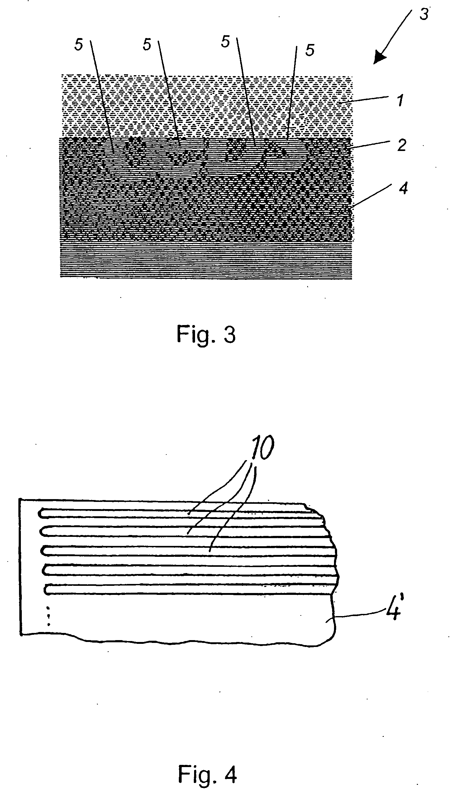
[0006] According to one aspect of the present invention, a security document, such as a banknote, includes an optical security area having a first periodic optical structure and a security sign provided on the security area and configured to circumscribe a second periodic optical structure which is disposed in offset relationship to the first periodic optical structure, and a see-through element for enhancing recognizability of the security sign on the security area, wherein the see-through element is constructed for arrangement on the security area to thereby define a viewing zone which covers part of the security sign so as to render this part of the security sign visible by the naked eye.
[0008] According to another feature of the present invention, the see-through element may be sized to cover half of the security area. In this way, the position of the security sign can be detected at a glance.
[0009] According to another feature of the present invention, the see-through element has an optical structuring which can be similar or identical to the first or second periodic optical structures. The two-dimensional configuration required for the first and second periodic structures is thus also applicable to the applied see-through element, so that the thickness of the see-through element can be kept to a minimum. The see-through element therefore projects only marginally beyond the security document and does not adversely affect the use of the security document. The security area can, however, also be arranged in a recess of the security document surface and the see-through element can be embedded in this recess.
[0010] According to another feature of the present invention, the first periodic optical structure and the second periodic optical structure may each be configured as parallel grid-type lines, parallel line grid, or point grid parallel grid-type lines, with the distance between the adjacent grid-type lines, parallel line grids or point grids being 1.5 times a line thickness of the grid-type lines, parallel line grids or point grids. Ruled gratings and grids of this kind can be produced very easily by printing, and lead to a clearly recognizable contrast.
[0014] This kind of see-through element can be hot-stamped in a simple manner onto the surface of the security document in accordance with the invention. Moreover, the film can be a component of a hologram film which is hot-stamped onto the security document. The hologram and the see-through element can be applied in one operation onto the security document.

Problems solved by technology

This constitutes per se a security feature that is difficult to imitate because—as a result of the moire effect—a characteristic effect is obtained which cannot be imitated by a mere color copy.

Method used


Image

  • Security document with an optical security area
  • Security document with an optical security area
  • Security document with an optical security area

Examples


Embodiment Construction

[0026] Throughout all the Figures, same or corresponding elements are generally indicated by same reference numerals. These depicted embodiments are to be understood as illustrative of the invention and not as limiting in any way. It should also be understood that the drawings are not necessarily to scale and that the embodiments are sometimes illustrated by graphic symbols, phantom lines, diagrammatic representations and fragmentary views. In certain instances, details which are not necessary for an understanding of the present invention or which render other details difficult to perceive may have been omitted.

[0027] It is to be understood by persons skilled in the art that the term “security document” is used here in a generic sense and the principles described in the following description with respect to the security document are equally applicable to any other type of value-bearing document which generally follows the concepts outlined here. Examples include banknotes, checks, ...


PUM


Abstract

A security document, such as a banknote, includes an optical security area having a first periodic optical structure and a security sign provided on the security area and configured to circumscribe a second periodic optical structure which is disposed in offset relationship to the first periodic optical structure. Arranged on the security area is a see-through element for enhancing recognizability of the security sign on the security area. The see-through element defines hereby a viewing zone which covers part of the security sign so as to render this part of the security sign visible by the naked eye.

Description

CROSS-REFERENCES TO RELATED APPLICATIONS [0001] This application is a continuation of prior filed copending PCT International application no. PCT / AT03 / 00135, filed May 12, 2003, which designated the United States and on which priority is claimed under 35 U.S.C. §120, the disclosure of which is hereby incorporated by reference, and which claims the priority of Austrian Patent Application, Serial No. A 736 / 2002, filed May 14, 2002, pursuant to 35 U.S.C. 119(a)-(d).BACKGROUND OF THE INVENTION [0002] The present invention relates, in general, to a security document, such as a banknote, for example. [0003] Nothing in the following discussion of the state of the art is to be construed as an admission of prior art. [0004] Security documents of a type involved here include an optical security area and a security sign which is also known as “hidden images” and is normally difficult to recognize by the naked eye. Examples of security signs include hidden words, images or geometrical figures. ...

Claims


Application Information

Patent Timeline
IPC IPC(8): B42D15/00
CPCB42D25/29B42D2035/16B42D25/318
Inventor DEINHAMMER, HARALDLOOS, FRANZ
Owner OESTERR BANKNOTEN UND SICHERHEITSDRUCK
Learn More