Authentication of identification documents using digital watermarks

Inactive Publication Date: 2005-05-05
DIGIMARC CORP +1
View PDF99 Cites 78 Cited by
  • Summary
  • Abstract
  • Description
  • Claims
  • Application Information

AI Technical Summary

Benefits of technology

[0010] The watermark components may be defined, embedded and extracted in different domains. Examples of domains include spatial, temporal and frequency domains. A watermark may be defined in a domain by specifying how it alters the host signal in that domain to effect the

Problems solved by technology

One challenge to the developers of watermark embedding and reading systems is to ensure that the watermark is detectable even if the watermarked media content is transformed in some fashion.
The watermark may be corrupted intentionally, so as to bypass its copy protection or anti-counterfeiting functions, or unintentionally through

Method used


Image

  • Authentication of identification documents using digital watermarks
  • Authentication of identification documents using digital watermarks
  • Authentication of identification documents using digital watermarks

Examples


Embodiment Construction

1.0 Introduction

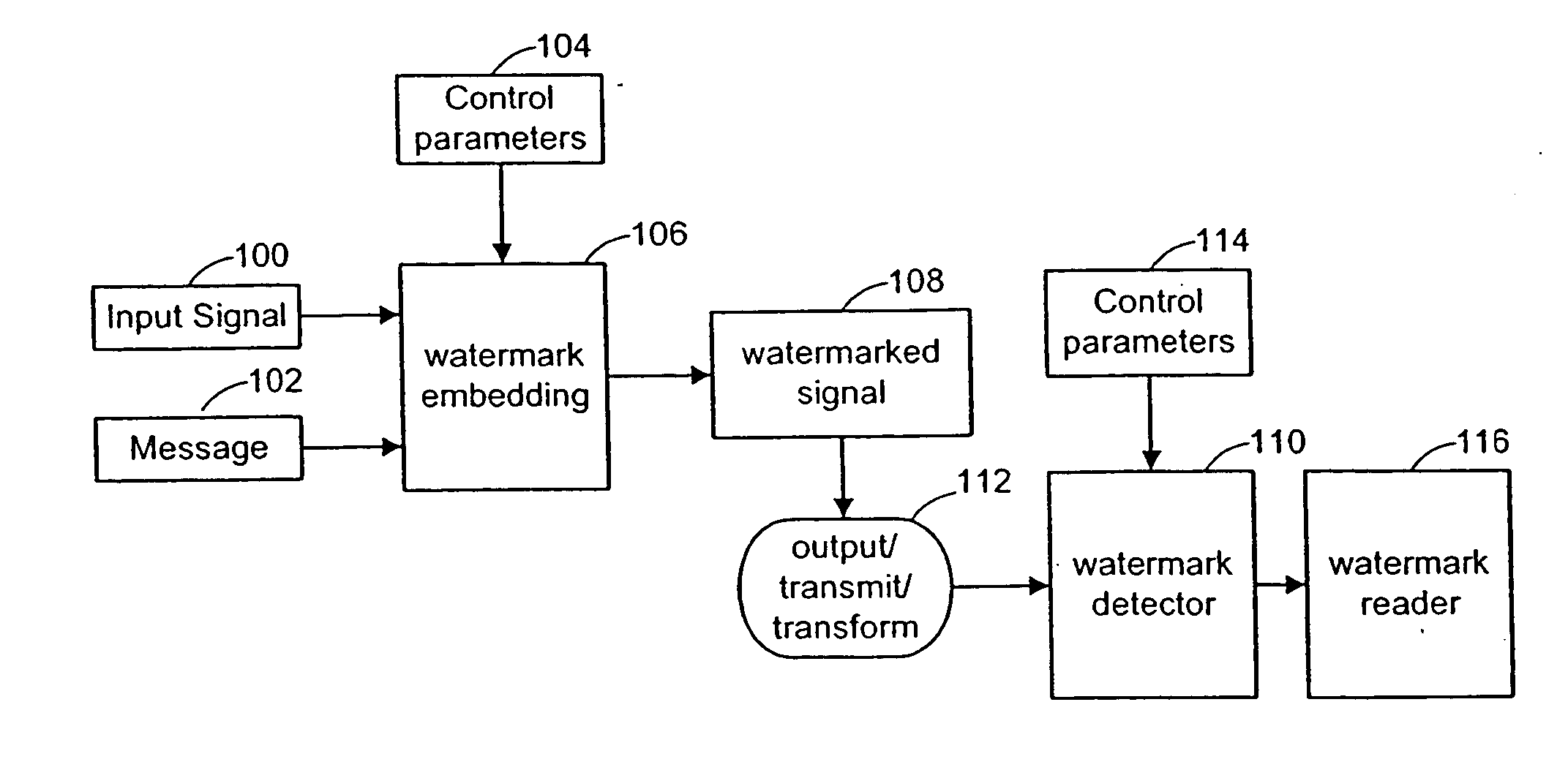
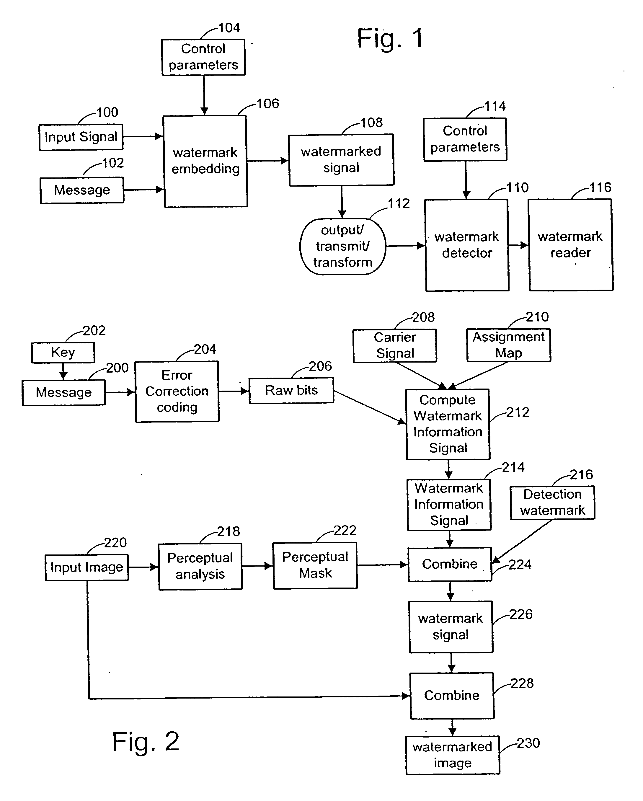
[0042] A watermark can be viewed as an information signal that is embedded in a host signal, such as an image, audio, or some other media content. Watermarking systems based on the following detailed description may include the following components: 1) An embedder that inserts a watermark signal in the host signal to form a combined signal; 2) A detector that determines the presence and orientation of a watermark in a potentially corrupted version of the combined signal; and 3) A reader that extracts a watermark message from the combined signal. In some implementations, the detector and reader are combined.

[0043] The structure and complexity of the watermark signal can vary significantly, depending on the application. For example, the watermark may be comprised of one or more signal components, each defined in the same or different domains. Each component may perform one or more functions. Two primary functions include acting as an identifier to facilitate detecti...


PUM


Abstract

Digital watermark methods for encoding auxiliary data into a host signal are used to authenticate physical and electronic objects. In one implementation, an identification document includes electronic circuitry. The electronic circuitry includes an image of an authorized bearer of the identification document. The image includes first digital watermarking having a plural-bit identifier. In some cases, the identification document includes a printed image of the authorized bearer of the identification document. The printed image includes second digital watermarking therein. The first digital watermarking and the second digital watermarking can be cross-correlated for authentication of the identification document.

Description

RELATED APPLICATION DATA [0001] This patent application is a division of U.S. patent Ser. No. 09 / 837,564, filed Apr. 17, 2001 (published as U.S. No. 2002-0009208 A1), which claims the benefit of U.S. Provisional Patent Application No. 60 / 198,849, filed Apr. 21, 2000. The Ser. No. 09 / 837,564 application also claims priority to U.S. Provisional patent application No. 60 / 198,138 filed Apr. 17, 2000. The Ser. No. 09 / 837,564 application is also a continuation in part of U.S. patent application Ser. No. 09 / 503,881, filed Feb. 14, 2000, which is a continuation in part of application Ser. No. 09 / 186,962, filed Nov. 5, 1998, which is a continuation of application Ser. No. 08 / 649,419, filed May 16, 1996, (now U.S. Pat. No. 5,862,260), which is a continuation in part of application Ser. No. 08 / 637,531, filed Apr. 25, 1996, (now U.S. Pat. No. 5,822,436), which is a continuation in part of application Ser. No. 08 / 512,993 filed Aug. 9, 1995, (abandoned in favor of FWC Ser. No. 08 / 763,847, now iss...

Claims


Application Information

Patent Timeline
IPC IPC(8): G06T1/00
CPCG06T2201/0052G06T1/0064
Inventor CARR, J. SCOTTLOFGREN, NEIL E.SEDER, PHILLIP ANDREW
Owner DIGIMARC CORP
Why Eureka
Try Eureka