Angular tool and holding block

a technology of holding blocks and angular tools, which is applied in the field of cutting tools, can solve the problems of difficult replacement of cutting bits, wear and enlargement of recesses, and the inability to satisfactorily retain cutting bits in the cutting bit supporting member, so as to facilitate the replacement of cutting bits and the retention of the cutting bi

Active Publication Date: 2005-05-12
LATHAM WINCHESTER E
View PDF19 Cites 17 Cited by
  • Summary
  • Abstract
  • Description
  • Claims
  • Application Information

AI Technical Summary

Benefits of technology

[0012] The movement of the retainer within the opening and the amount of force applied to the cutting bit by the retainer can be controlled by a tension element that can extend through an opening in a second of the lateral surfaces aligned with the line of action. The tension element can extend between the retainer and the second lateral surface to apply a force drawing the retainer into the tool holder opening. The tension element can be a screw threaded fastener having a head that can be positioned outside the second lateral surface of the tool holder. The tension element can also have a threaded portion engaged in a threaded opening in the retainer. Surface to surface contact between the retainer and the cutting bit can be facilitated by making the opening in the tool holder first lateral surface circular and the retainer per

Problems solved by technology

Particularly in the presence of abrasive dust from the roadway mining other similar operation, the rotational movement of such cutting bits acts to wear and enlarge the recesses in which the cutting bit is received.
If the wear becomes sufficient, the cutting bit may no longer be satisfactorily retained in the cutting bit supporting

Method used


Image

  • Angular tool and holding block
  • Angular tool and holding block
  • Angular tool and holding block

Examples


Embodiment Construction

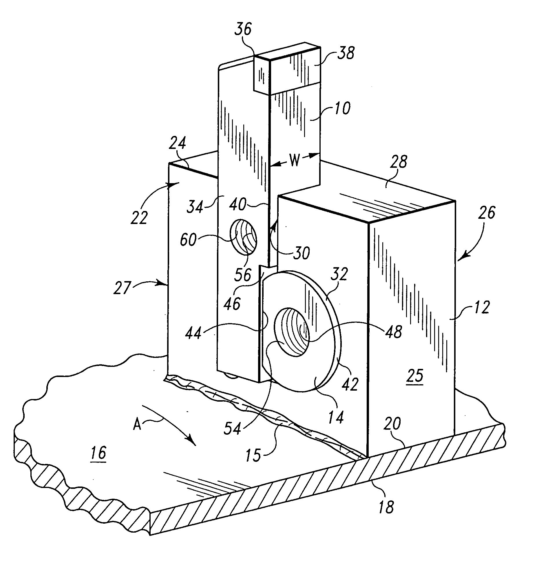
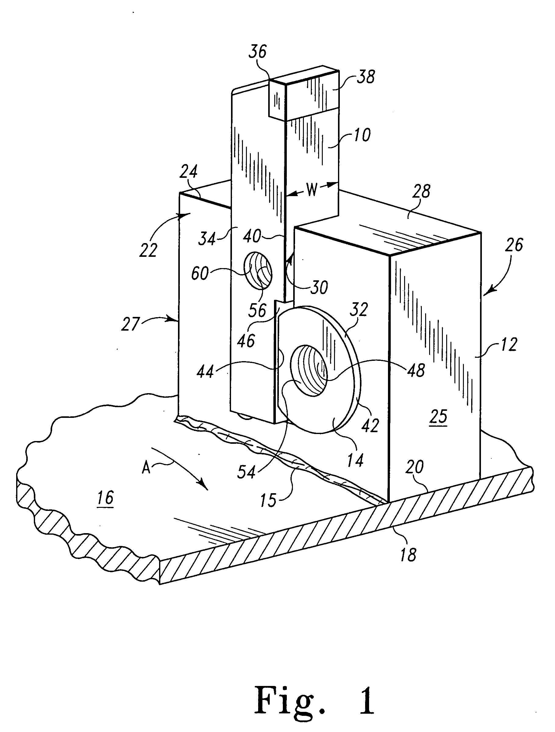
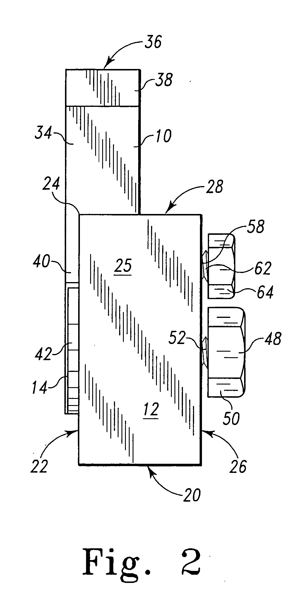
[0027] A combined cutting tool or bit 10, holder 12 and retainer 14 are shown in FIGS. 1-3. The holder 12 is shown in FIG. 1 to be fixed by weld 15 to a curved surface 16 of a rotary driven cutter drum 18 for movement in the direction of arrow A. The tool holder 12 includes a base 20 that can be curved to be arcuately concave to match the curved surface 16 of the drum 18. The tool holder base 20 can also include a flat portion as shown in FIG. 3 that can be selected to set at a desired rake angle for the tool or bit 10. A first lateral surface 22 extends upward from the base 20 to an uppermost edge 24 of the lateral surface 22. A second lateral surface 26 is provided on the opposite side of the holder 12. The second lateral surface 26 can be parallel and similarly dimensioned to the first lateral surface 22. A top or crown surface 28 connects the uppermost edges 24 of the lateral surfaces 22 and 26. The top or crown surface 28 can be planar or curved. A front surface 25 connects the...


PUM

PropertyMeasurementUnit
Angleaaaaaaaaaa
Angleaaaaaaaaaa
Angleaaaaaaaaaa

Abstract

A cutting tool holder, a cutting bit, and a retainer maintaining the cutting bit at a prescribed position relative to the tool holder. The cutting bit is received in a slot located in a first lateral surface that extends through the top surface. The retainer is received in an opening included in the first lateral surface that intercepts the slot. The retainer includes a planar tapered surface that contacts an upwardly and laterally facing oblique surface on a lower end of the cutting bit to hold the lower end of the cutting tool in contact with a lower surface of the slot.

Description

BACKGROUND [0001] 1. Technical Field [0002] The present invention relates generally to a cutting tool used with a holder having a seat to receive the cutting tool including a separate fastener to clamp the tool in the seat. The invention particularly relates to cutter tools and holding blocks for such tools that can be employed in coal mining, road cutting, trenching, trash-shredding and tree stump removing apparatus. [0003] 2. General Background [0004] In general, roadway cutting, coal mining, tree stump removing, and similar equipment known in the prior art includes a rotary driven cylindrical comminuting drum which acts to scarify and to mine the target area such as the top portion of an asphaltic road surface in situ. The rotary driven drum can include flighting on the drum which acts to collect the mined material toward the center of the drum where it can be removed. Often the mined material is remixed with additional bituminous material and thereafter re-deposited as a newly f...

Claims


Application Information

Patent Timeline
IPC IPC(8): E21C35/193
CPCY10T407/227E21C35/1936Y10T83/9464
Inventor LATHAM, WINCHESTER E.
Owner LATHAM WINCHESTER E
Why Eureka
Try Eureka