Drawbar for power-operated industrial truck

a technology for industrial trucks and pulleys, which is applied in the direction of hand carts, steering controls, lifting devices, etc., can solve the problems of difficult operation and inability to ensure optimal accessibility

Active Publication Date: 2005-05-12
JUNGHEINRICH AG
View PDF13 Cites 11 Cited by
  • Summary
  • Abstract
  • Description
  • Claims
  • Application Information

AI Technical Summary

Benefits of technology

[0006] The object of the invention is to produce a drawbar for an industrial truck in which the control elements allow optimal accessibility, optionally also when the drawbar is in the folded up position.

Problems solved by technology

In the known drawbar embodiments the control elements of the drawbar head can only be reached with difficulty in the folded up position of the drawbar and generally cannot be observed which makes the operation more difficult.
The control elements are generally predominantly round or square in their contour shape and therefore constructed in such a shape that they do not guarantee optimal accessibility of the hand grasping the drawbar head in every position.

Method used


Image

  • Drawbar for power-operated industrial truck
  • Drawbar for power-operated industrial truck
  • Drawbar for power-operated industrial truck

Examples


Embodiment Construction

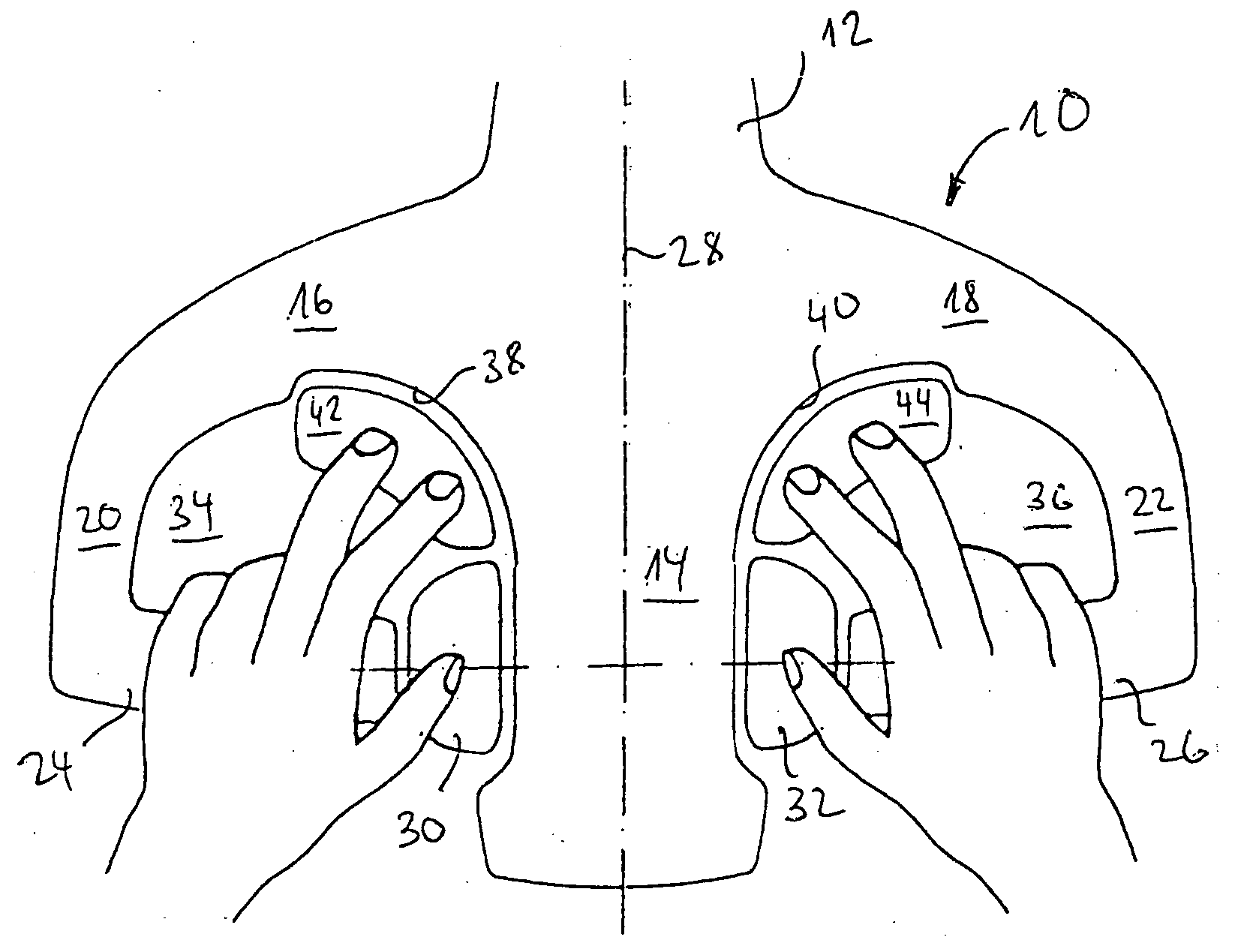
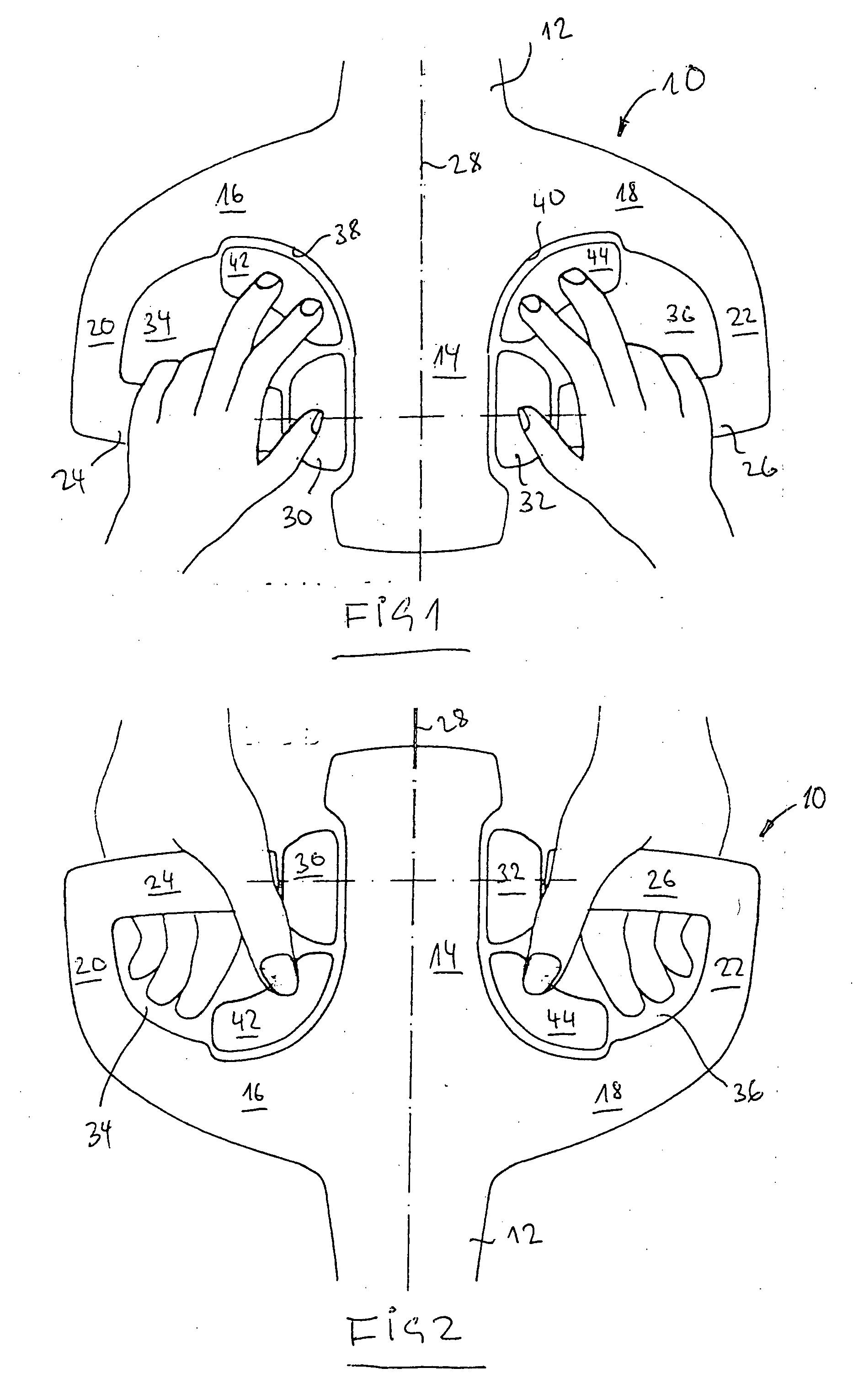
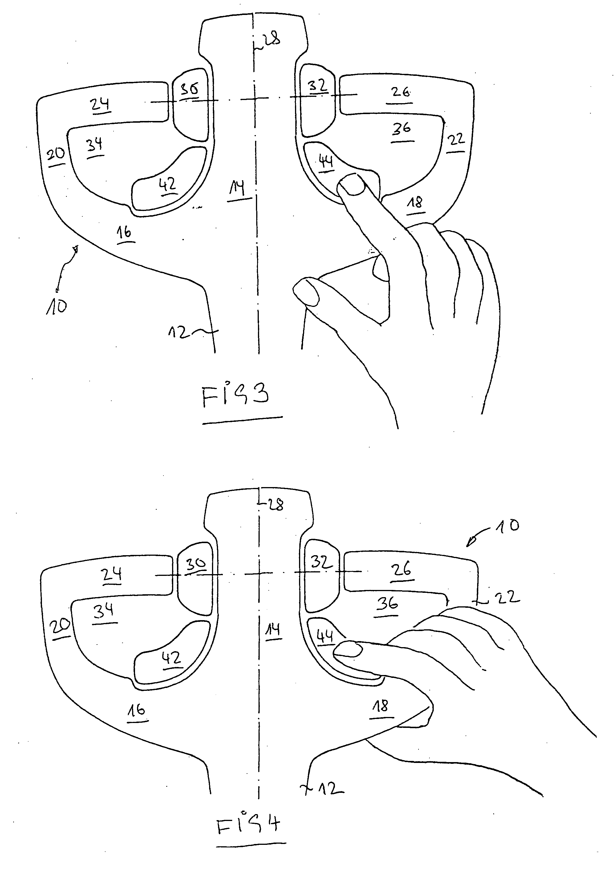
[0034] A drawbar head is indicated in FIGS. 1 to 10 which is generally referred to by 10 and in its basic configuration is similarly constructed in all the Figures. It is connected via a shoulder 12 to a drawbar handle or drawbar tube of an industrial truck not shown. The drawbar handle is pivotally mounted about a horizontal axis and covers a larger angular range from an approximately upright position to an approximately flat position of the drawbar. In the extension of the drawbar or the shoulder 12 a so-called horn 14 extends and carrier sections 16, 18 are attached to opposing faces of the horn 14. The carrier sections 16, 18 are radiused and merge with arm sections 20, 22 which extend approximately parallel to the horn 14 at a distance therefrom. At the other end the arm sections 20, 22 are connected to rod-like grips 24, 26 which extend approximately perpendicular to the central axis 28 of the drawbar head 10 in the direction of the horn 14, but end at distance therefrom. The ...


PUM


Abstract

A drawbar for power-operated industrial trucks with a drawbar handle which can be pivoted about a horizontal axis in a large angular range between an approximately upright position and a position inclined obliquely to vertical. The drawbar includes a drawbar head arranged at a free end of the drawbar handle, the head including a horn arranged in the extension of the drawbar handle, rod-like grips extending on both sides of the horn and approximately transversely thereto that are connected to carrier sections connected to the horn on both sides via arm sections attached to the end of a grip. The arm and carrier sections form a protective yoke with grip openings and at least one control element for a function of the industrial truck on one grip opening is arranged in the vicinity of the associated carrier section, such that it can be actuated from above by pressure from one finger, even when the hand grasps the rod-like grip facing it. The control element is constructed and arranged, such that with an approximately upright drawbar handle, it can even be actuated from the lower face of the drawbar head by finger or thumb pressure.

Description

FIELD OF THE INVENTION [0001] The invention relates to a drawbar for a power-operated industrial truck according to claims 1, 2 and 5. BACKGROUND OF THE INVENTION [0002] Hand controlled lift trucks or front loaders have a drawbar with which the industrial truck is steered. The steering of the drawbar takes place at the support for the pivotable drive wheel of the materials handling truck. At the free end a drawbar head is provided which has a plurality of actuation members for operating the industrial truck. Thus for example drive switches are provided, actuation elements for the lifting and lowering operation and the horn. It is known from EP 0 751 060 to attach grips on both sides of a horn, which is arranged in the extension of the drawbar handle, and to attach them to both sides of the horn via a protective bracket. The connection is made via arm sections extending approximately parallel to the horn and via carrier sections which in turn extend approximately parallel to the grip...

Claims


Application Information

Patent Timeline
Patent Type & Authority Applications(United States)
IPC IPC(8): B62B5/06B62D1/14B62D51/00B66F9/20
CPCB62B5/06B62B5/063Y10T74/2028B62D51/001B66F9/20B62D1/14
Inventor DAVID, BERNDLOHMANN, HELMUTNIEBUHR, MICHAELPREHN, VOLKMAR
Owner JUNGHEINRICH AG
Why Eureka
Try Eureka