Wave energy conversion system

a wave energy and conversion system technology, applied in the direction of electric generator control, machines/engines, mechanical equipment, etc., can solve the problems of large installation capacity, general disenchantment in the viability of wave energy conversion, and the inability to meet the requirements of large-scale operation,

Inactive Publication Date: 2005-05-12
HIRSCH WILLIAM WALTER
View PDF55 Cites 133 Cited by
  • Summary
  • Abstract
  • Description
  • Claims
  • Application Information

AI Technical Summary

Benefits of technology

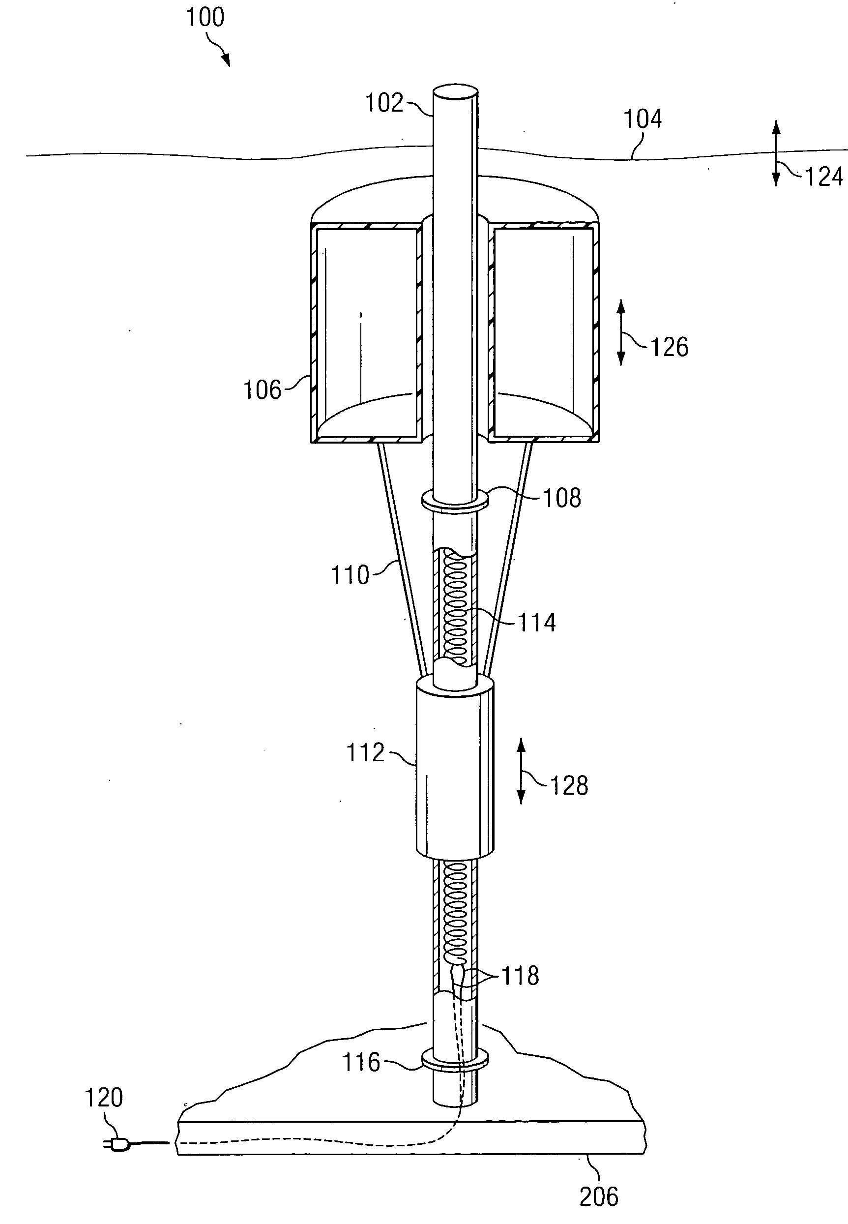
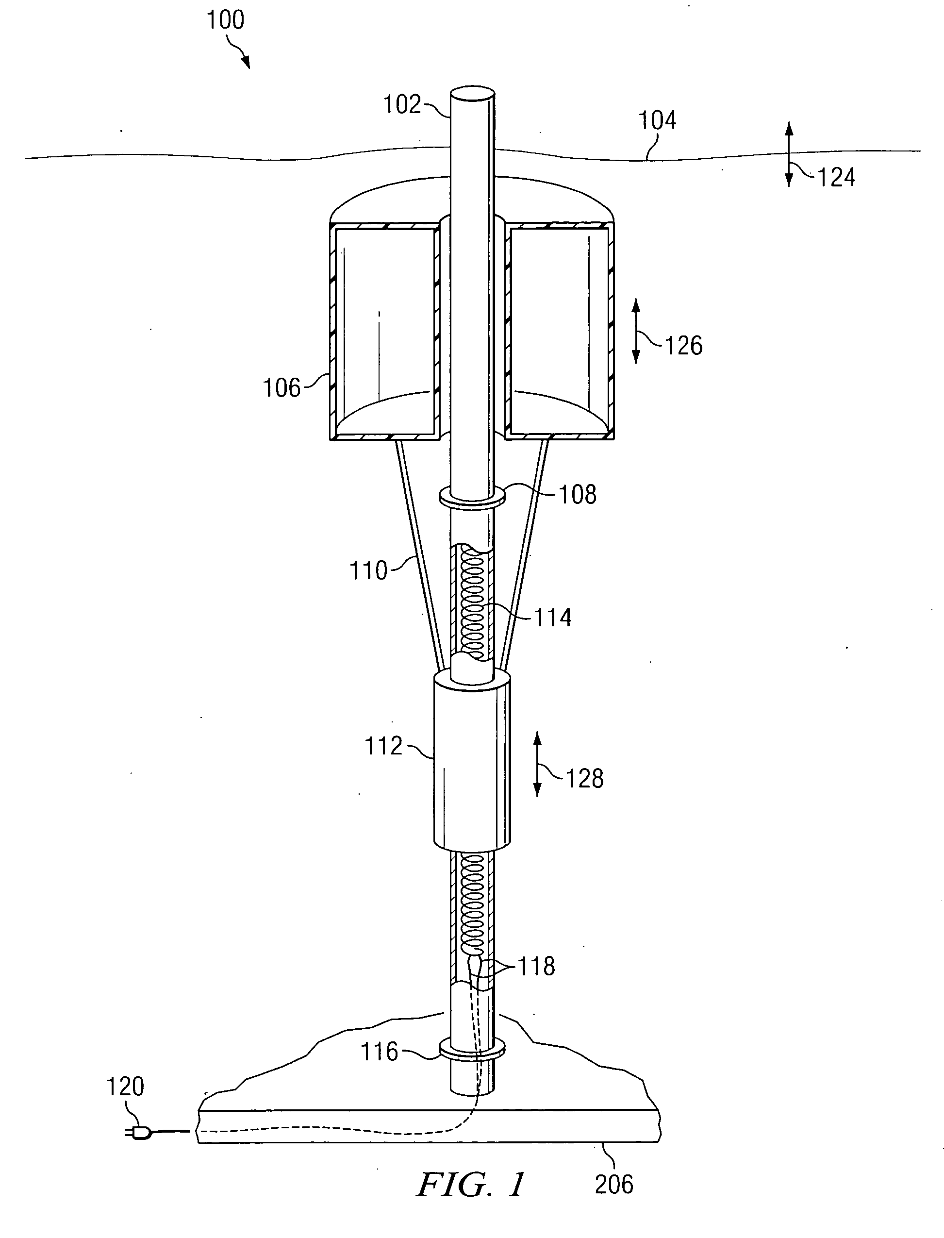
[0063] A wave energy conversion system converts wave energy within a wave medium into electrical energy. The wave energy conversion system includes a base substantially connected to a wave-medium floor, a tidal platform connected to said base and a tidal float connected to said tidal platform. An axle is connected to said tidal platform with an inductive coil positioned within the axle, such that an axis of the inductive coil is parallel to the axle. A magnetic sleeve includes a magnetic sleeve opening, such that the axle passes through the magnetic sleeve opening. A float member is connected to said magnetic sleeve. A wave moving through the wave causes displacement of the float member, causing the magnetic sleeve to move relative to the inductive coil and generate electrical energy within the inductive coil.

Problems solved by technology

A lack of practical solutions or reasonable prospects of efficient and robust technologies, plus declining oil prices, eventually led to a general disenchantment in the viability of wave-energy conversion.
It is, however, unlikely that any one such installation will have an installed capacity greater than two megawatts and the number of suitable sites has to be extremely limited.
The partially filled vessel will start to sink.
This is a heavily engineered device, one that will not readily flex with the lateral movements of water as found below waves, it is not independent of the seabed and is not independent of tidal changes in mean sea level.
A common problem with existing devices designed to harvest significant amounts of energy from the sea is their complexity and cost.
Most devices proposed are very demanding in terms of engineering design, deployment and maintenance.
Other known devices which are used in the marine environment, although not designed for the conversion of wave energy to usable power include devices designed to pump fluids from the sea-bed.
Known Wave Energy Converters tend to be expensive, and have limited prospects for survival in extreme conditions.
The small size of the devices typically used in military systems makes it difficult to collect a useful amount of power since natural energy usually occurs as a “flux”, and the amount available for collection depends on the physical capture area.
The amount of energy or power available in waves is enormous and this power is generally recognized by the damage caused.
In other words, most devices which have been designed for capturing or converting the energy of waves to useful work have been destroyed or damaged by that very energy.
This is at least partly due to the irregularity of waves which can cause jerky or irregular motion of wave energy devices.
Moreover, storms frequently occur during which time wave action can become violent, thus destroying installations erected for converting the energy of the waves to useful work.
Other prior art devices are not efficient in operation and convert only a very small portion of the available wave energy.
Thus, while devices floating on the surface of a body of water may be utilized to extract some of the energy of the waves themselves, these devices are not able to extract energy from the moving water itself.
All such prior art devices capture or convert only a small portion of the available power in waves and in many cases are not durable enough to withstand the forces encountered in the ocean's waters or are not cost efficient.
The disadvantage of this device is the large number of input and output elements which makes this device very complicated.
Furthermore, the flow should surmount the local resistances in its inflow in the input and outflow from the output collector or manifold as a result of which there occurs a decrease in the harnessed energy.
When the level is very low, part of the gas can flow out of the converters and this results in a loss of part of the compressed air.
Conversely, when we have a high level and a little volume of the gas cushion, the latter is inferior in its role as buffer and energy accumulator.
Furthermore, this device cannot be directed at a specified angle towards the wave front, and in this way an important reserve for increasing its smoothness of operation and improving its efficiency cannot be utilized.
One limitation of this system is that it can utilize only the amount of ocean water that flows into the tank opening to provide the dynamic force on the propeller blade, rather than being able to use the full force of the ocean wave.
Ocean thermal energy conversion is limited to tropical regions, such as Hawaii, and to a portion of the Atlantic coast.
Furthermore, only a few have been tested at sea, in ocean waves, rather than in artificial wave tanks.
The cost, however, of electricity transmission from deep ocean sites is prohibitively high.
There are currently no firm plans to deploy any of these projects.
As of the mid-1990s, wave energy conversion was not commercially available in the United States.
The technology was in the early stages of development and was not expected to be available within the near future due to limited research and lack of federal funding.

Method used


Image

  • Wave energy conversion system
  • Wave energy conversion system
  • Wave energy conversion system

Examples


Embodiment Construction

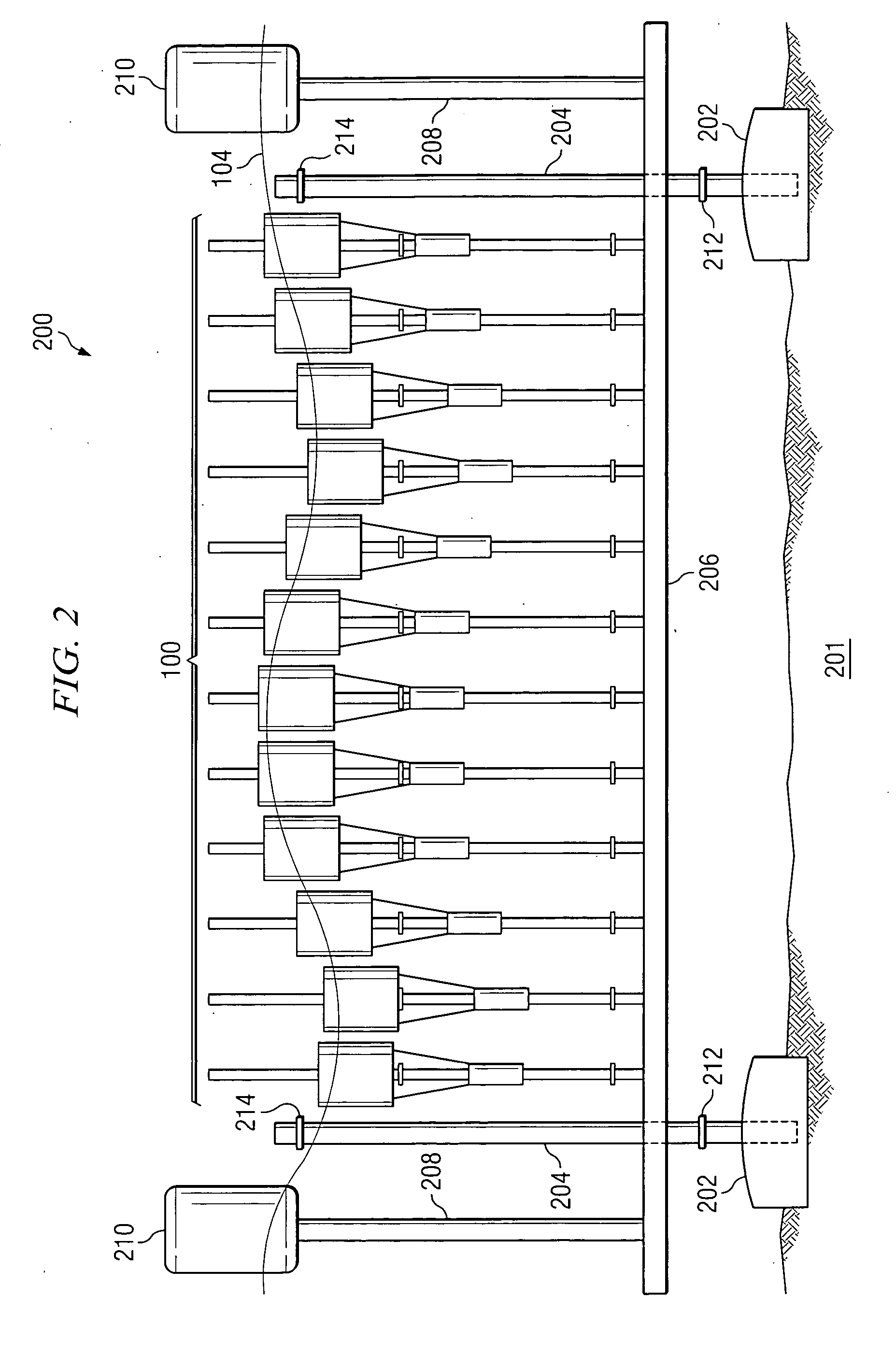
[0085] Referring now to the drawings, wherein like reference numbers are used to designate like elements throughout the various views, several embodiments of the present invention are further described. The figures are not necessarily drawn to scale, and in some instances the drawings have been exaggerated or simplified for illustrative purposes only. One of ordinary skill in the art will appreciate the many possible applications and variations of the present invention based on the following examples of possible embodiments of the present invention.

[0086] With reference to FIG. 1, a wave energy conversion device 100 in accordance with the preferred embodiment is shown. The wave energy conversion device 100 includes a generally vertically positioned central wave displacement axle 102.

[0087] The central wave displacement axle 102, in accordance with the preferred embodiment, is a hollow rigid pole. The diameter of the central wave displacement axle will typically be about one inch, ...


PUM


Abstract

A wave energy conversion system converts wave energy within a wave medium into electrical energy. The wave energy conversion system includes a base substantially connected to a wave-medium floor, a tidal platform connected to said base and a tidal float connected to said tidal platform. An axle is connected to said tidal platform with an inductive coil positioned within the axle, such that an axis of the inductive coil is parallel to the axle. A magnetic sleeve includes a magnetic sleeve opening, such that the axle passes through the magnetic sleeve opening. A float member is connected to said magnetic sleeve. A wave moving through the wave causes displacement of the float member, causing the magnetic sleeve to move relative to the inductive coil and generate electrical energy within the inductive coil.

Description

TECHNICAL FIELD OF THE INVENTION [0001] The invention relates to wave-energy conversion devices, particularly to point absorber wave-energy conversion systems, comprising in part an underwater device which derives power from buoyancy variations arising from changes in pressure caused by waves and / or changes in the level on the surface above and which reacts against a platform that changes level in accordance with tidal level changes. BACKGROUND OF THE INVENTION [0002] The petroleum crisis in the early 1970's was the impetus for significant innovation in wave energy conversion systems. A lack of practical solutions or reasonable prospects of efficient and robust technologies, plus declining oil prices, eventually led to a general disenchantment in the viability of wave-energy conversion. [0003] Research continued at a few largely academic centers and over the past twenty-five years a great deal has been learned. Both theoretical understanding of sea waves and technical expertise in r...

Claims


Application Information

Patent Timeline
Patent Type & Authority Applications(United States)
IPC IPC(8): F03B13/10F03B13/12F03B13/18H02P9/04
CPCF03B13/1845Y02E10/38F03B13/1855F05B2220/707F05B2240/40Y02E10/30
Inventor HIRSCH, WILLIAM WALTER
Owner HIRSCH WILLIAM WALTER
Why Eureka
Try Eureka