Electric blower

a blower and electric technology, applied in the direction of positive displacement liquid engines, piston pumps, liquid fuel engines, etc., can solve the problems of low cooling effect of the wiring, weak cooling effect of the field wiring at large temperature difference between the field wiring at the fan side and the opposite side of the fan, so as to improve the rise of the field wiring temperature and reduce the weight

Inactive Publication Date: 2005-05-12
NIH DEITR
View PDF6 Cites 2 Cited by
  • Summary
  • Abstract
  • Description
  • Claims
  • Application Information

AI Technical Summary

Benefits of technology

[0012] An object of the present invention is to provide a compact and light electric blower which is improved in rise in wiring temperature while securing the efficiency as the blower.
[0015] The gap capable of passing air is provided between the coil end between the slots of the field wiring and the field core, and the spool is provided with the wall surface formed between the field core and the motor frame so as to narrow the airflow section that forms the outer periphery portion of the field wiring, thereby generating the first flow which is guided to the field wiring by the wall surface of the spool at the opposite side of the fan to cool the wiring after flowing along the motor frame from the gap between the wall surface of the spool disposed at the end surface of the field core and the motor frame. And a second flow which is guided by the wall surface protruded to the outer periphery of the field wiring of the spool, passes through the gap capable of passing air that is formed between the coil end between the slots of the field wiring and the field core, and cools the field wiring and the armature wiring. Thus, the advantageous effect of improving the temperature rise can be obtained without reducing the airflow efficiency with each of the first and second flows having high capability of cooling the wirings.
[0016] As a result, the rise in the wiring temperature which becomes the problem in terms of reduction in size of the electric blower and rise in power consumption can be improved, and the electric blower with light weight and high reliability can be obtained.
[0022] According to this configuration, the air passing between the field core and the armature core and flowing to the opposite side of the fan is discharged from the wind hole of the motor frame after hitting the exposed portion of the field wiring exposed between the raised columns at the spool, thus contributing to improvement of rise in the field wiring temperature at the opposite side of the fan. Further, the coil end of the wiring can be made small, thus contributing to the reduction in weight. The outward deviation of the wiring becomes small, thus obtaining the advantageous effect of facilitating mounting a component such as a temperature detecting sensor to the outer periphery portion of the wiring.

Problems solved by technology

Further, the air flowing near the motor frame distant from the wirings is discharged outside the motor without performing the operation of cooling the wirings, and therefore cooling effect of the wiring is especially low at the opposite side of the fan.
Therefore, there exists a problem that the cooling effect of the field wiring at the opposite side of the fan is weak, and the temperature difference between the field wirings at the fan side and the opposite side of the fan is large.
Further, there exists another problem that the pressure loss of the airflow increases, and the blower efficiency reduces because the sectional area through which the air discharged from the fan can enter the motor becomes small.

Method used


Image

  • Electric blower
  • Electric blower
  • Electric blower

Examples


embodiment 1

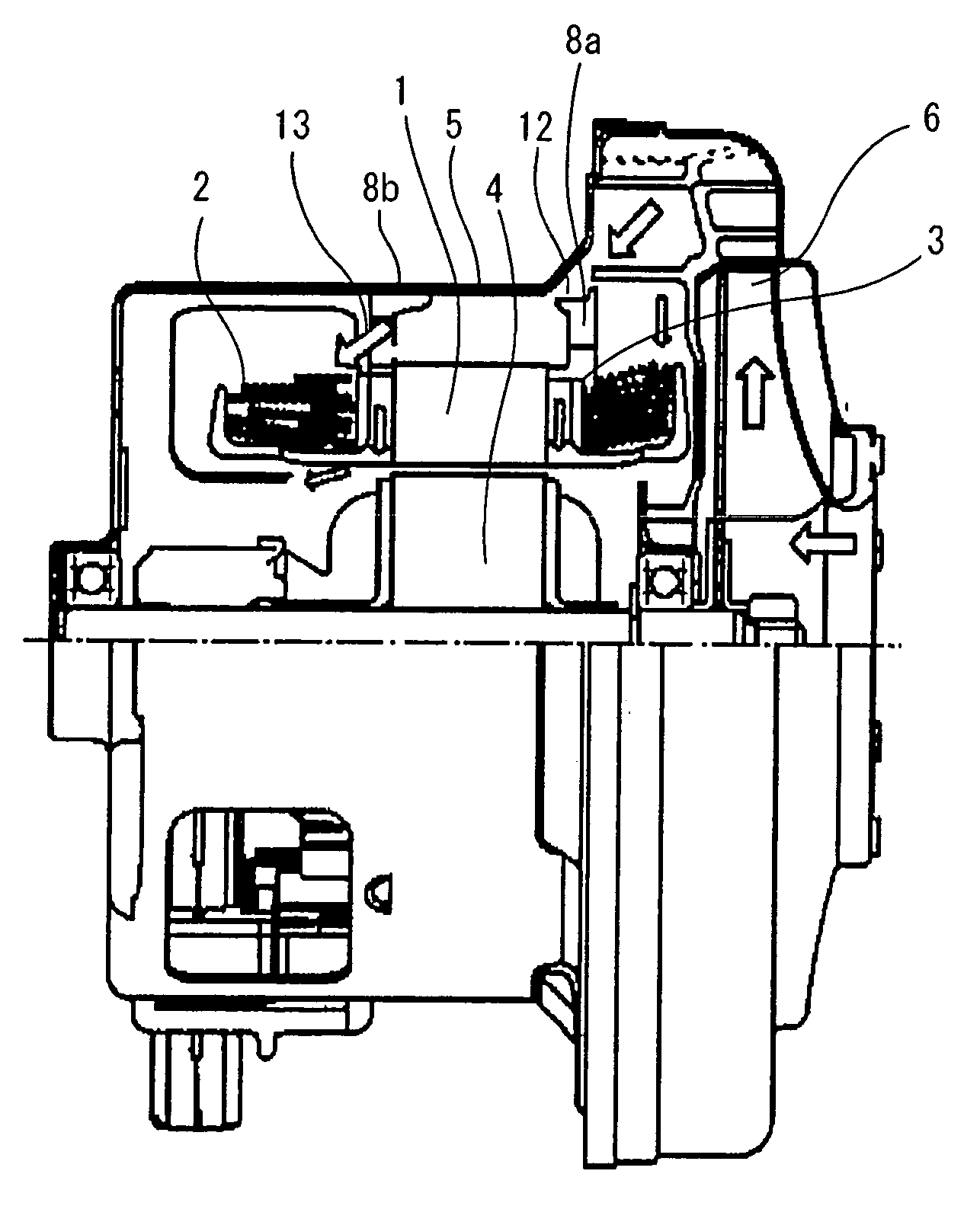
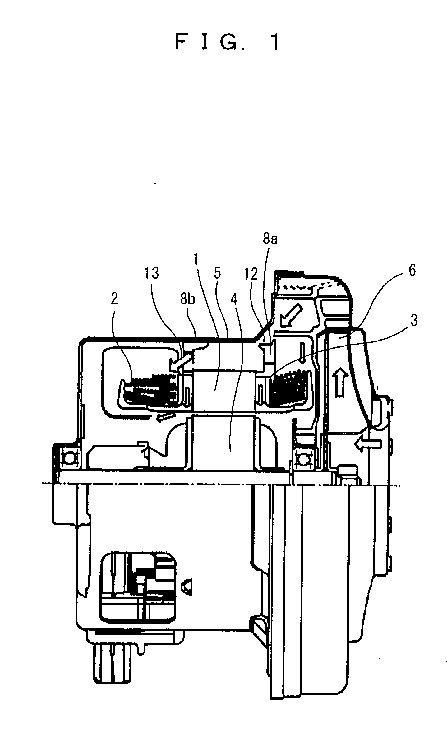
[0032]FIG. 1 shows a half cross-sectional view of an electric blower according to one embodiment of the present invention. In FIG. 1, reference numeral 1 denotes a field core, reference numeral 2 denotes a field wiring, reference numeral 3 denotes a spool, reference numeral 4 denotes an armature, reference numeral 5 denotes a motor frame, reference numeral 6 denotes a rotary fan, reference numerals 8a and 8b denote wall surfaces of the spool.

[0033] Here, a flow of air which flows into the motor will be explained. The air discharged from the rotary fan 6 flows inside the motor along the motor frame 5, and is separated into a first flow (thick arrow) which is guided to the field winding 2 by the wall surface 8b of the spool 3 at the opposite side of the fan after flowing along the motor frame from a gap 12 between the wall surface 8a of the spool 3 disposed at the end surface of the field core 1 and the motor frame 5, a second flow (thin arrow) which is guided by the wall surface 8a ...

embodiment 2

[0036]FIG. 4 is a half cross-sectional view of the electric blower according to a second embodiment of the present invention. A plurality of raised columns 9 extending inward from the inner diameter of the field core 1 are included at the spool 3 provided at the end surface of the field core 1 at the opposite side from the fan, and the innermost diameter of an exposed portion of the field wiring 2 exposed between the raised columns 9 is made smaller than the inner diameter of the field core 1.

[0037]FIG. 5 is a view showing a spool of an electric blower according to a second embodiment of the present invention. The spool 3 includes a terminal stand for holding a tip end of the field wiring 2 wound across the field core 1 and the spool 3 and a connection terminal, and two raised columns 9 for holding and fixing the coil end of the wiring are provided and connected to each other at the center.

embodiment 3

[0038]FIG. 6 shows an electric cleaner loaded with the electric blower at a body 54. The electric cleaner sucks air including dust from a suction port via a hose 52, and the suction force is obtained by rotating a centrifugal fan 6 mounted to an output shaft of the electric blower. The electric blower with excellent wiring cooling ability and high blowing efficiency is used to obtain a large suction force with a small size and light weight.


PUM


Abstract

A compact and light electric blower which is improved in wiring cooling capability without reducing the airflow efficiency. The electric blower includes a spool attached to end surfaces of a field core fixed to a motor frame of which outer periphery portion is in an approximately cylindrical shape, and field wiring each wound across the field core and the spool, wherein a gap capable of passing air is formed between the coil end between slots of the field wiring and the field core, and each spool is provided with a wall surface which narrows the airflow section formed between the field core and the motor frame while forming a periphery portion of the field wiring.

Description

TECHNICAL FIELD OF THE INVENTION [0001] The present invention relates to an electric blower included in an electric appliance such as an electric cleaner, and particularly relates to an electric blower enhanced in the effect of reducing wiring temperature by allowing suction air to flow inside an electric motor. BACKGROUND OF THE INVENTION [0002] A half cross-sectional view of a conventional electric blower is shown in FIG. 7. In FIG. 7, reference numeral 1 denotes a field core, reference numeral 2 denotes a field winding, reference numeral 3 denotes a spool, reference numeral 4 denotes an armature assembly, reference numeral 5 denotes a motor frame, reference numeral 6 denotes a rotary fan, and reference numeral 7 denotes an air guide. For the electric motor for driving the rotary fan 6 to obtain a suction force, a comutator motor which easily rotates at high speed is used. FIG. 8 shows a plan view only of an electric motor section of a conventional electric blower without a rotary...

Claims


Application Information

Patent Timeline
Patent Type & Authority Applications(United States)
IPC IPC(8): H02K3/24H02K7/14F04D29/58H02K9/06
CPCH02K9/06H02K7/14H02K3/24
Inventor SHIMASAKI, TETSUOFUJIKI, SHIGEAKIUENO, MAKOTO
Owner NIH DEITR
Why Eureka
Try Eureka