System and method for mounting sensors and cleaning sensor apertures for out-the-window displays

a technology sensors, which is applied in the field of system and method for cleaning sensor apertures for out-the-window displays, can solve the problems of high angle of attack at lower speeds, inability to ensure the use of windowsowless cockpits in commercial or general use, and inability to achieve the effect of ensuring the safety of the cockpi

Active Publication Date: 2005-05-12
SUPERSONIC AEROSPACE INT
View PDF12 Cites 72 Cited by
  • Summary
  • Abstract
  • Description
  • Claims
  • Application Information

AI Technical Summary

Benefits of technology

[0010] In one embodiment, sensors mounted beneath the nose of the aircraft provide inputs to a display system that

Problems solved by technology

Although the crews provided positive feedback on the capabilities of the system, windowless cockpits are not expected to be certified for use in commercial or general aircraft by the FAA until the year 2007 or beyond.
Additionally, most contemporary supersonic aircraft designs feature a modified delta wing optimized for high-speed flight that results in high angles of attack at lower speeds.
The long nose and high angle of attack at low airspeeds impairs the FAA required forward visibility of the flight crew during some phases of operation.
The droop nose configuration requires additional weight and space

Method used


Image

  • System and method for mounting sensors and cleaning sensor apertures for out-the-window displays
  • System and method for mounting sensors and cleaning sensor apertures for out-the-window displays
  • System and method for mounting sensors and cleaning sensor apertures for out-the-window displays

Examples


Embodiment Construction

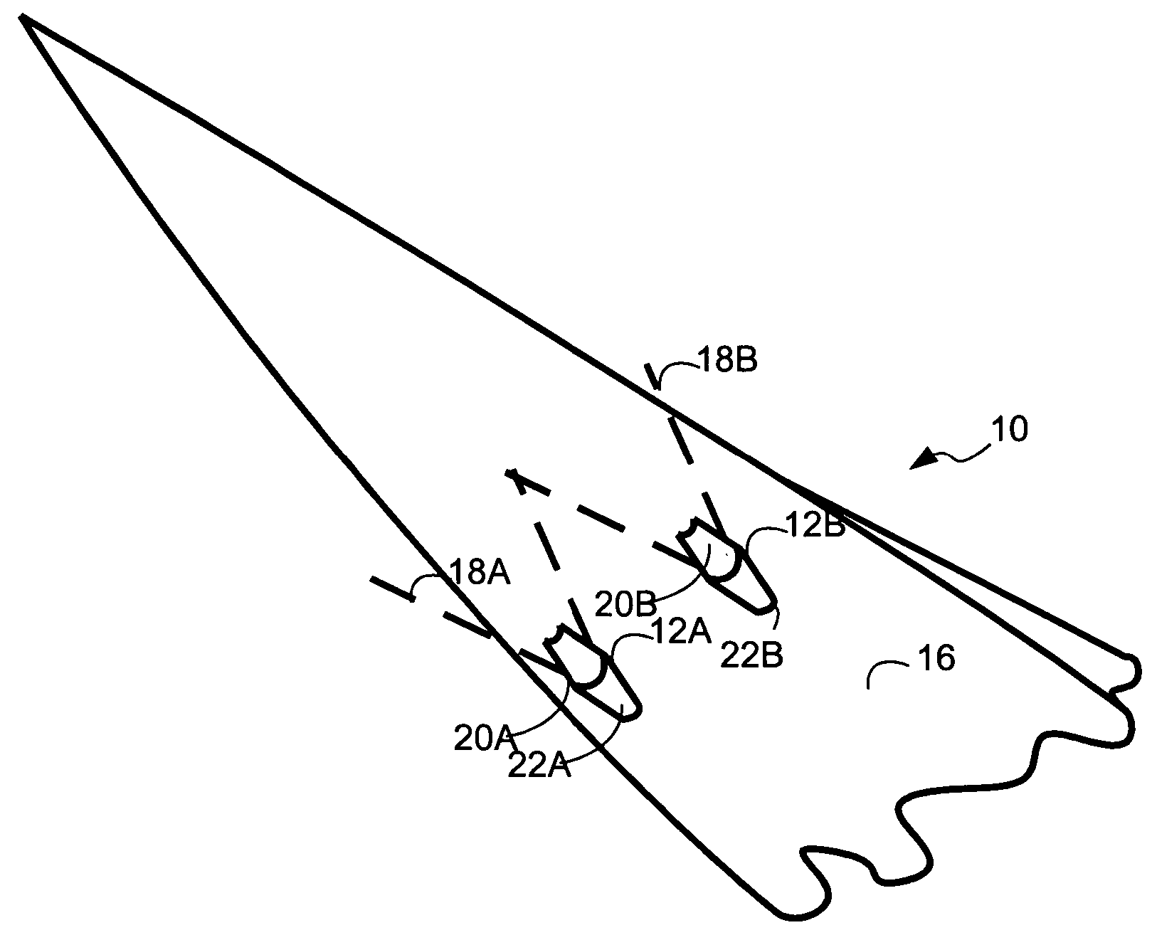
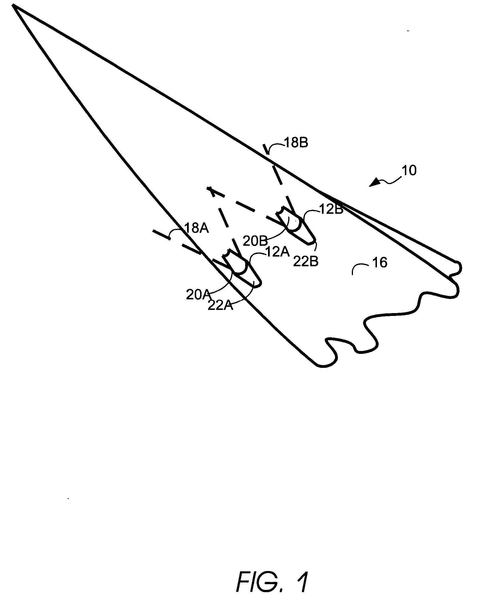
[0028]FIG. 1 provides an isometric view of the underside of an aircraft 10. Although FIGS. 1-4 depict a protective sensor mount used on an aircraft. This sensor mount may be used to provide out-the-window displays for devices such as aircraft, trains, boats, and other types of devices where it is useful to have visual images of scenery, traffic, obstacles, and other objects surrounding the device. As shown in FIG. 1, two protective sensor housings 12 protect sensors 14. Sensor housings 12 are mounted on lower surface 16 of the nose of aircraft 10. Each sensor provides a field of view 18 through transparent aperture 20. Fairings 22 provide a smooth continuous transition between the sensor housings and the fuselage of aircraft 10.

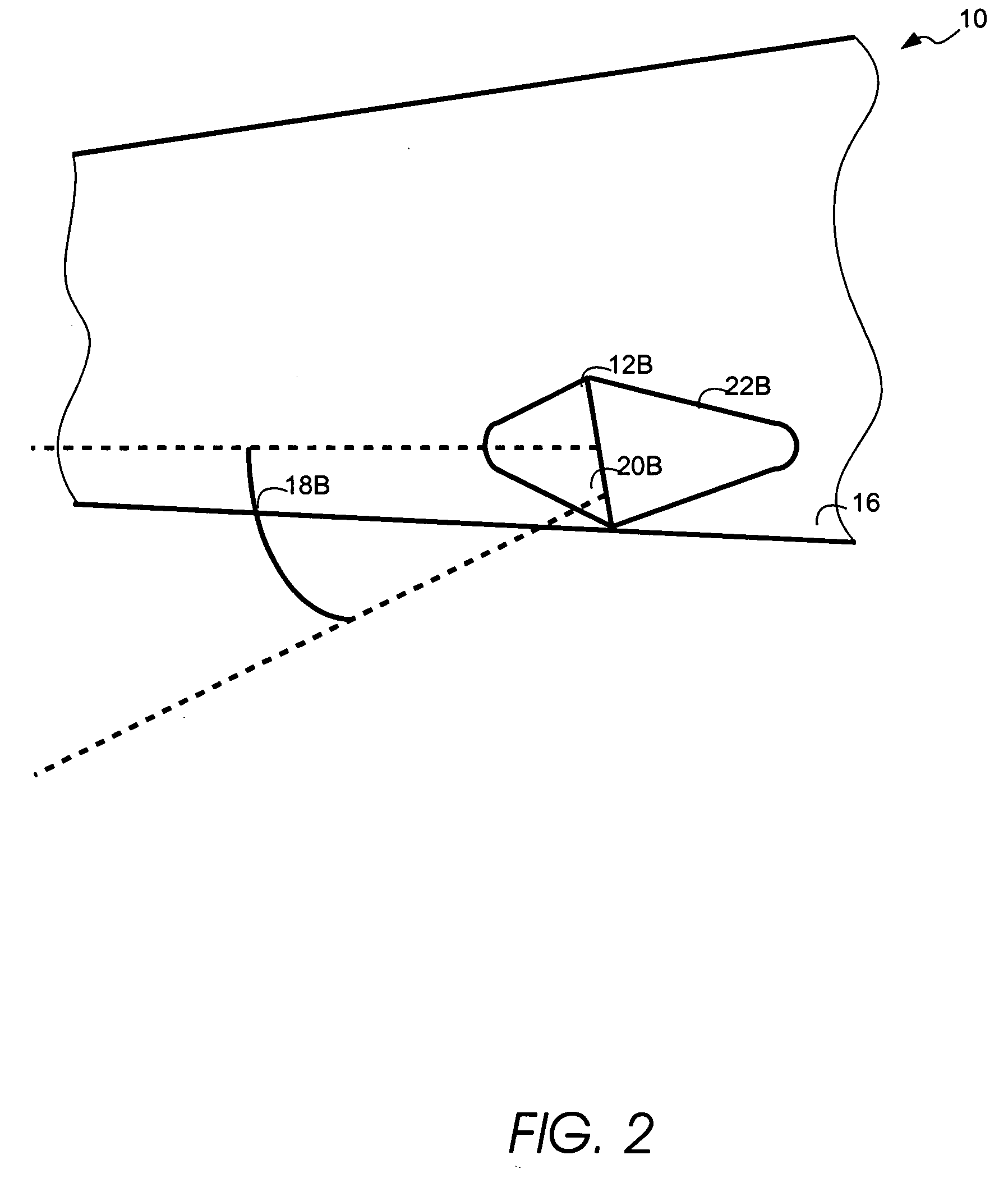
[0029] Similarly, FIG. 2 provides a left side view of aircraft 10 that further depicts sensor housing 12. As previously described, sensor housings 12 may be mounted on lower surface 16 of the nose of aircraft 10. The sensor contained within the housing is pr...


PUM


Abstract

Multiple sensors capture images representing scenery outside an aircraft or other type of vehicle for use within a visual display system. A protective housing encloses the sensors. This protective housing includes a transparent aperture through which the sensor captures images. A cleaning mechanism removes obstructions from the transparent aperture in order to provide continuous images representing scenery outside the aircraft through an operator display.

Description

BACKGROUND OF THE INVENTION [0001] Many devices, such as aircraft, are typically designed to provide a view of the out-the-window scene for at least one operator to operate the device. In the past, a view of the scenery outside the device was provided through passive means, such as a cockpit windshield, or artificial means through sensors and displays. [0002] Synthetic Vision Systems (SVS) present a completely artificial computer-generated view of the external environment to the crewmember(s). SVS displays are typically based on static geographical and cultural data supplemented by dynamic traffic information. Some implementations of SVS use Global Positioning Satellite (GPS) data to register the data base information dynamically to the aircraft's position and altitude. Supplemental sensors may be used to confirm the GPS position data or provide additional data (e.g., other aircraft, weather events, ground equipment). SVS can use both head-up and head-down displays. Displays typical...

Claims


Application Information

Patent Timeline
IPC IPC(8): B64D47/08G01D7/08G06F3/14G09G5/00
CPCB64D47/08G06F3/1431G01D7/08
Inventor BERSON, BARRY L.BIALECKI, LARRY J.BUCK, PETER A.
Owner SUPERSONIC AEROSPACE INT
Why Eureka
Try Eureka