
Device used for detecting clamping force of processed object and method thereof

a technology of processing object and clamping force, which is applied in the direction of measurement device, force/torque/work measurement apparatus, instruments, etc., can solve the problems of inconvenient adjustment of the clamping force of the pivotal rod, and the inability to perform standardized steps or procedures, so as to prevent the breakage of the processed object, reduce the loss of product and equipment damage, and facilitate standardized

Active Publication Date: 2005-05-19
NAN YA TECH
View PDF6 Cites 2 Cited by
  • Summary
  • Abstract
  • Description
  • Claims
  • Application Information

AI Technical Summary

Benefits of technology

[0010] Another object of the present invention is to provide a device used for detecting the clamping force of a processed object and a method thereof, whereby the clamping force of the processed object can be detected to avoid a too small clamping force, hence letting the processed object synchronously rotate with the pivotal rod.
[0011] Another object of the present invention is to provide a device used for detecting the clamping force of a processed object and a method thereof, whereby the clamping force of the processed object can be detected to avoid a too large clamping force, hence preventing breakage of the processed object during the processing process and thus reducing loss of product and damage of equipment.
[0012] Another object of the present invention is to provide a device used for detecting the clamping force of a processed object and a method thereof, whereby the step of adjusting the clamping force of the processed object can be easily standardized without the need of teach-and-learn of techniques and experiences.

Problems solved by technology

However, the above conventional apparatus and a method thereof for adjusting the clamping force of a processed object have the following drawbacks.
Therefore, the adjustment of the clamping force of the pivotal rods is inconvenient.
The operation cannot be performed with standardized steps or procedures.

Method used


Image

  • Device used for detecting clamping force of processed object and method thereof
  • Device used for detecting clamping force of processed object and method thereof
  • Device used for detecting clamping force of processed object and method thereof

Examples


Embodiment Construction

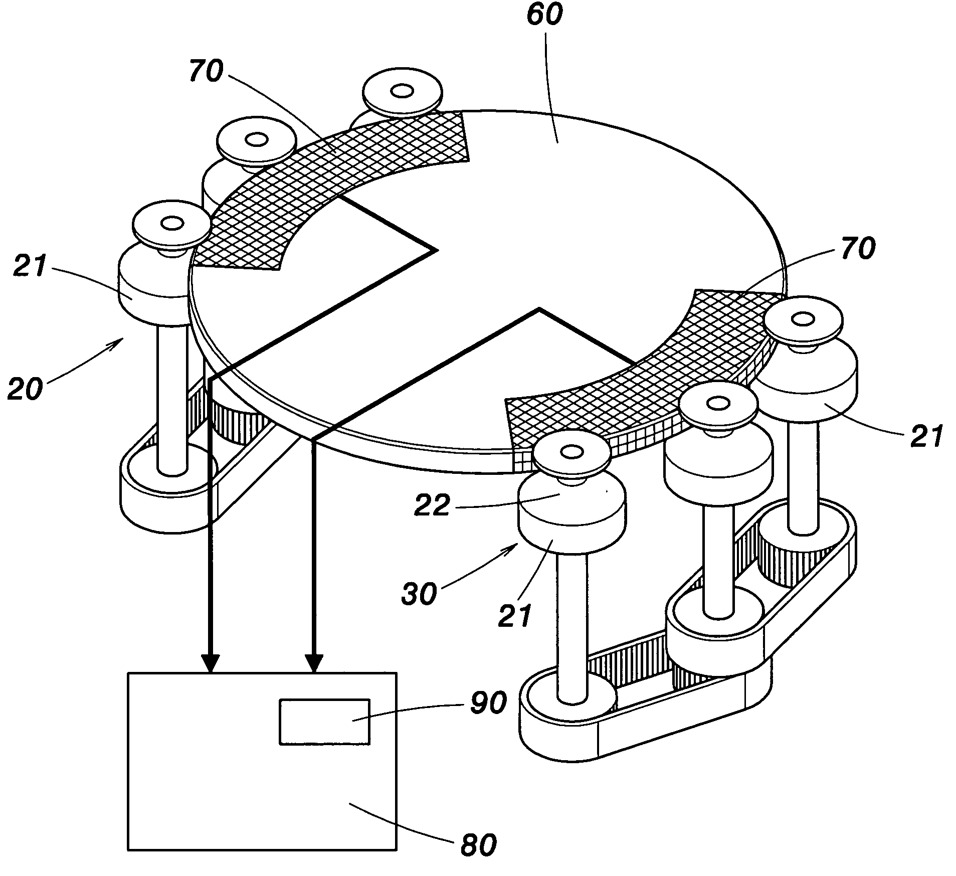
[0028] As shown in FIG. 4, the present invention provides a device used for detecting the clamping force of a processed object and a method thereof. The device detects the clamping force of a processed object 10 clamped by several pivotal rods 21. The device comprises a basis component 60, a pressure, detection component 70 disposed on the basis component 60 and a detection unit 80. The pressure detection component 70 is electrically connected to the detection unit 80. A display unit 90 electrically connected to the detection unit 80 is also provided. The basis component 60 having the pressure detection component 70 closely leans against and is placed between the pivotal rods 21 of the first and second pivotal rod sets 20 and 30 of a wafer cleaning apparatus. The pressure detection component 70 strains due to stress to generate variation of electric properties. The detection unit 80 detects the variation of electric properties of the pressure detection component 70, and the display ...


PUM

PropertyMeasurementUnit
clamping forceaaaaaaaaaa
longitudinal lengthaaaaaaaaaa
electric propertiesaaaaaaaaaa

Abstract

A device used for detecting the clamping force of a processed object and a method thereof are proposed. The device comprises a detection unit, a basis component and a pressure detection component disposed on the basis component. The basis component having the pressure detection component is closely placed between pivotal rods so that the detection unit can detect variation of electric properties of the pressure detection component to adjust the spacing between the pivotal rods, hence facilitating adjustment of the clamping force.

Description

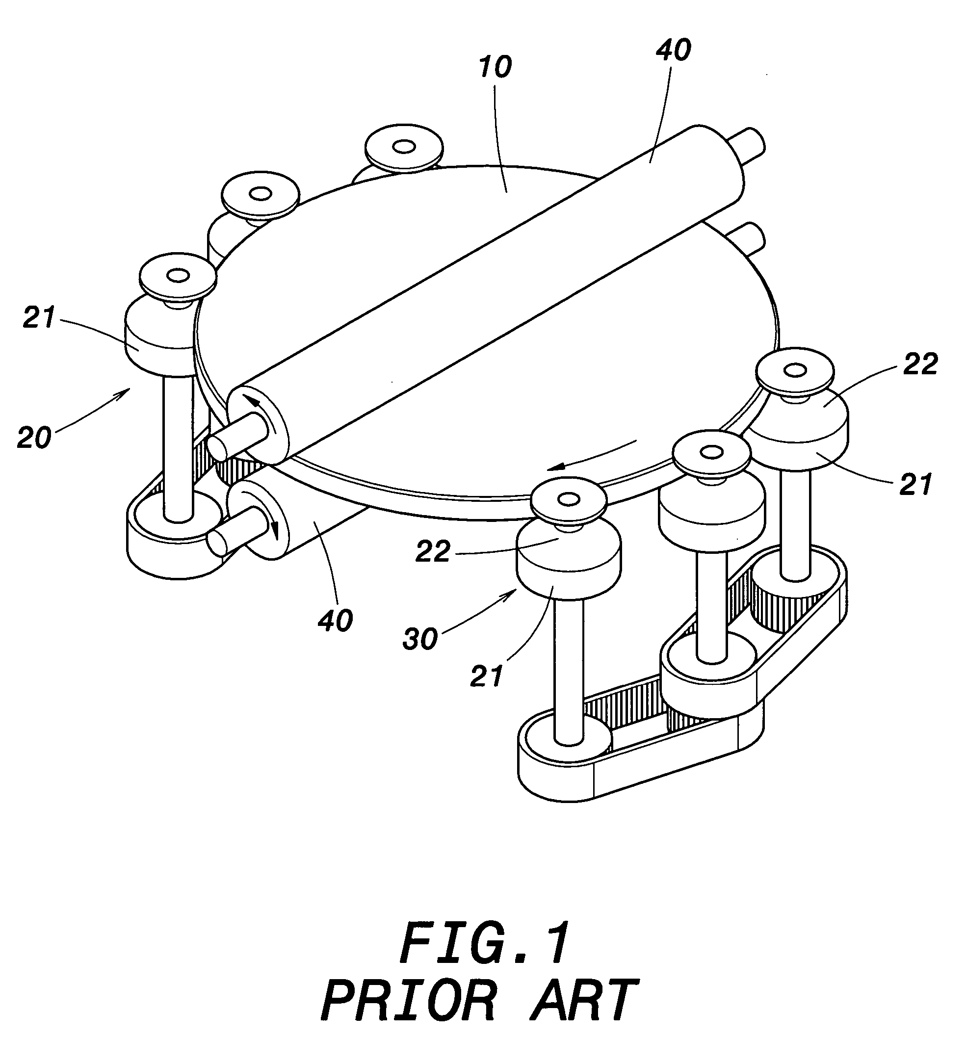
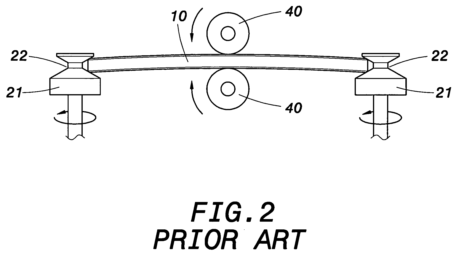
FIELD OF THE INVENTION [0001] The present invention relates to a device used for detecting the clamping force of a processed object and a method thereof, whereby the magnitude of the clamping force can be detected to adjust the spacing between pivotal rods, hence avoiding a too large or too small clamping force between the pivotal rods. BACKGROUND OF THE INVENTION [0002]FIGS. 1 and 2 show a wafer cleaning apparatus for cleaning the surface of a processed object 10. The processed object 10 is a wafer or another object. The wafer cleaning apparatus utilizes a first pivotal rod set 20 and a second pivotal rod set 30 to clamp the periphery of the processed object 10, and utilizes pivotal rods 21 of the pivotal rod sets 20 and 30 to support and rotate the processed object 10. There are also two cleaning wheels 40, which are respectively moved to upper and lower end faces of the processed object 10 and rotate to clean the processed object 10. [0003] As shown in FIG. 3, during the maintena...

Claims


Application Information

Patent Timeline
Patent Type & Authority Applications(United States)
IPC IPC(8): G01L5/00H01L21/00H01L21/687
CPCG01L5/009H01L21/68707H01L21/67288
Inventor CHEN, CHIH-KUNKUNG, YAO-HSIUNGLIN, CHUNG-MINWANG, SHAN-CHANGWANG, JIUN-BO
Owner NAN YA TECH
Learn More