Hinged solar collector for a light

Inactive Publication Date: 2005-05-19
WORLD FACTORY
View PDF11 Cites 72 Cited by
  • Summary
  • Abstract
  • Description
  • Claims
  • Application Information

AI Technical Summary

Benefits of technology

[0008] Therefore, it is an objective of the present invention to provide a hinged solar collector that can be adjusted to maximize the collection of solar energy, regardless of the position of the housing of the solar powered light.
[0009] The above objective is achieved by providing a solar collector that is positioned on

Problems solved by technology

Because the housing is usually positioned so that the solar powered light illuminates in a particu

Method used


Image

  • Hinged solar collector for a light
  • Hinged solar collector for a light
  • Hinged solar collector for a light

Examples


Embodiment Construction

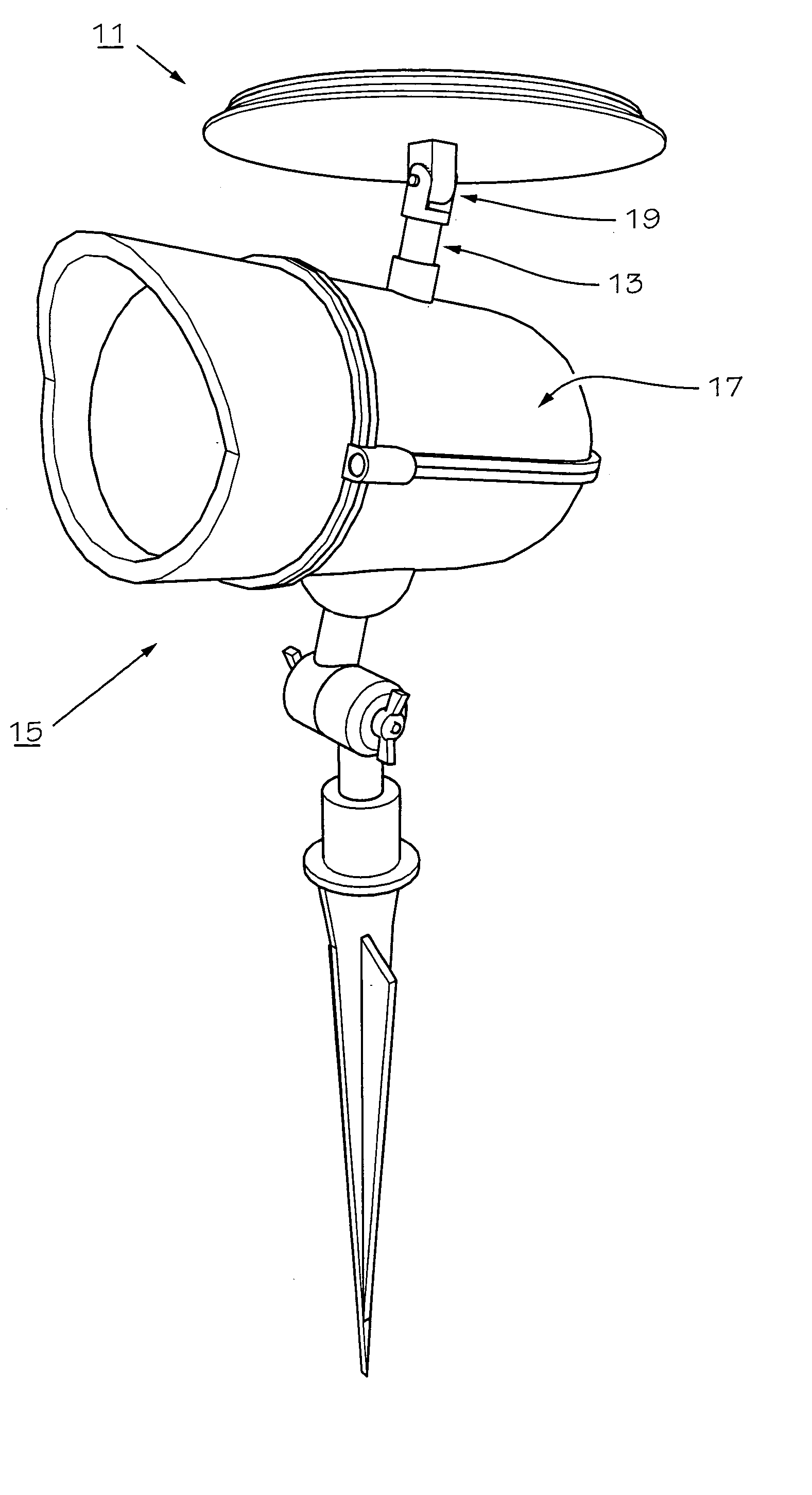
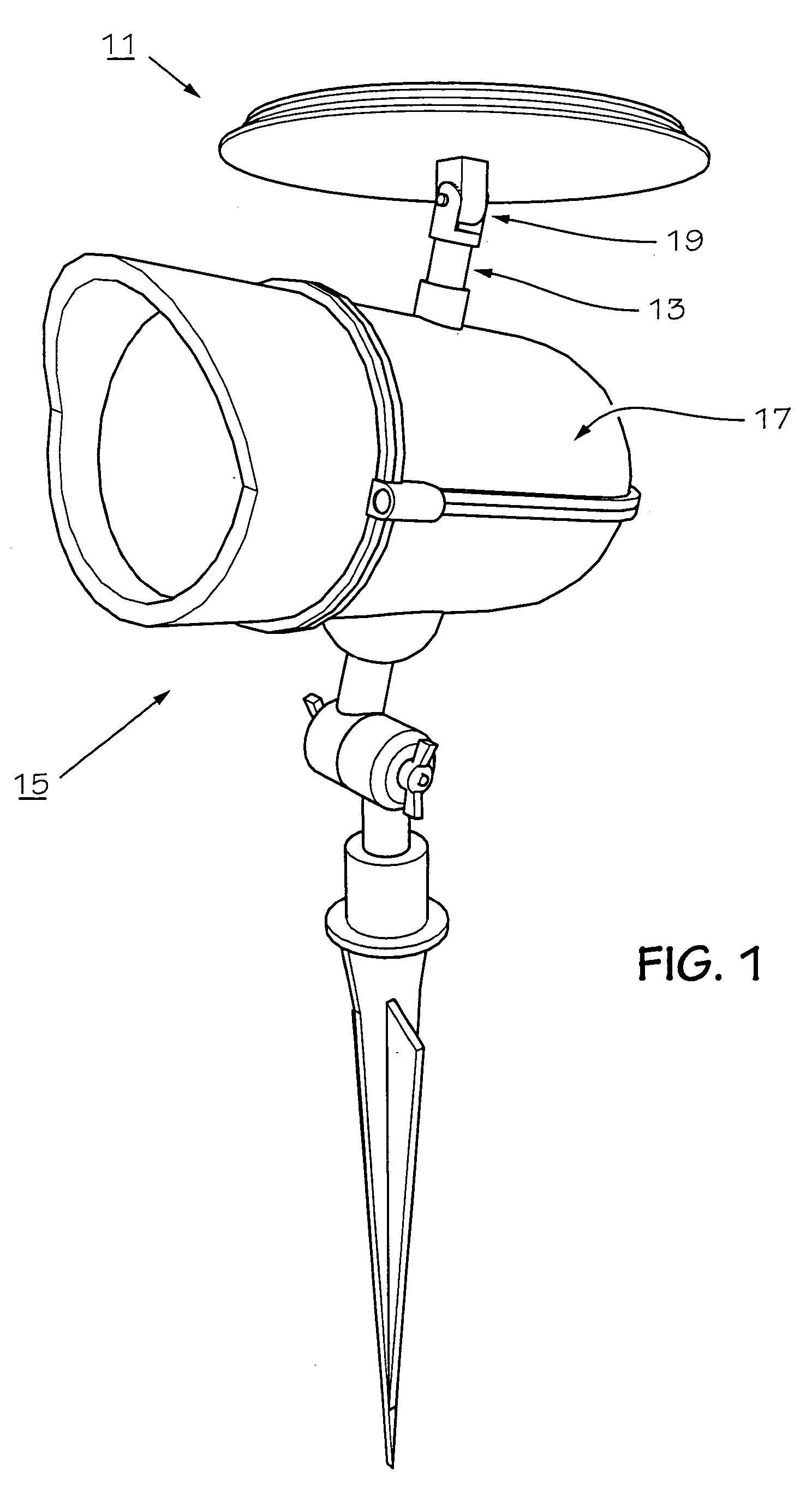
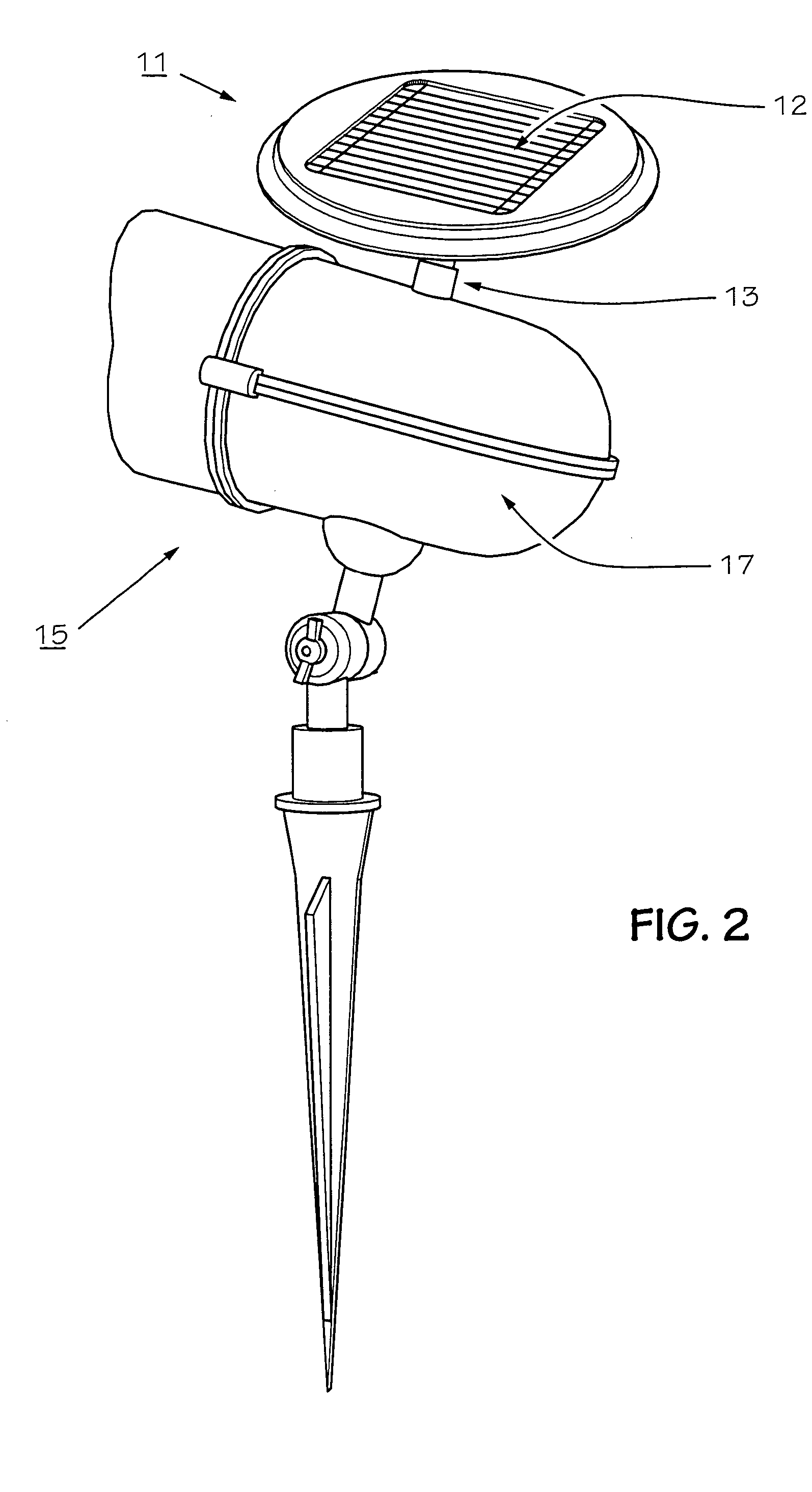
[0038] Referring to FIGS. 1 and 2 depict one embodiment of a hinged solar collector for a solar powered light is illustrated. As is shown a solar collector unit 11 is positioned at the top portion of a post 13. Solar collection unit 11 includes a conventional solar panel 12 and conventional wiring and circuitry (not shown) to allow the solar energy collected by solar panel to be converted into electrical energy and used to power or charge a solar powered light 15 or rechargeable battery (not shown). Post 13 is rotatably connected to a housing 17 of solar powered light 15 so that solar collector unit may rotate relative to housing 17. Post 13 includes a hinge means 19 that allows solar collector unit 11 to pivot about the lower portion of post 13 and rotate relative to housing 17. This configuration allows solar collector unit 11 to be positioned at a wide variety of angles relative to housing 17.

[0039] Because solar collector unit 11 can be positioned independent of housing 17, sol...


PUM


Abstract

A solar light is provided which includes a solar panel to convert solar energy to electrical energy to recharge a battery. A hinge allows a solar collector unit to pivot and rotate to allow positioning in a wide variety of angles. This enables the solar collector unit to be positioned perpendicular or more nearly perpendicular to sunlight rays while charging. A variety of hinges may be utilized, including a mono-axial hinge, a bi-axial hinge, a spherical hinge, or any other type of universal joint.

Description

BACKGROUND OF THE INVENTION [0001] 1. Field of the Invention [0002] The present invention relates to solar lights. In particular, the present invention relates to solar collectors for solar lights. [0003] 2. Description of the Prior Art [0004] Solar powered lights have been around for many years. The solar collector is typically installed on the top of the housing. [0005] Because the housing is usually positioned so that the solar powered light illuminates in a particular direction, the solar collector is rarely positioned to maximize the solar energy from the sun. [0006] For these reasons, many shortcomings remain in the area of solar powered lighting. SUMMARY OF THE INVENTION [0007] There is a need for a hinged solar collector that can be adjusted to maximize the collection of solar energy, regardless of the position of the housing of the solar powered light. [0008] Therefore, it is an objective of the present invention to provide a hinged solar collector that can be adjusted to m...

Claims


Application Information

Patent Timeline
IPC IPC(8): F21S8/00F21S9/03F24J2/54H01L31/00H01L31/042
CPCF21S9/032F21S9/035F21V21/0824F21W2131/10F21W2131/109F24J2/523H02S20/00F24J2/542F24J2/5431F24J2002/5489Y02E10/47Y02E10/50F24J2/525F21S2/00F21V17/02F24S25/10F24S25/617F24S30/452F24S30/48F24S2030/17H02S10/40H02S20/30Y02B20/72
Inventor PU, MINGQIANGKUELBS, GUSTAV P.
Owner WORLD FACTORY
Why Eureka
Try Eureka