Blown bottle with intrinsic liner

a bottle and liner technology, applied in the field of system for holding and dispensing liquids, can solve the problems of product failure, reduced reliability, unwanted particle generation in liquids, etc., and achieve the effect of diffusing the bond strength

Inactive Publication Date: 2005-05-19
ADVANCED TECH MATERIALS INC
View PDF20 Cites 82 Cited by
  • Summary
  • Abstract
  • Description
  • Claims
  • Application Information

AI Technical Summary

Benefits of technology

[0007] In a preferred embodiment, the adhesive contact between the rigid portion and the adhesive layer has a differing bond strength than the adhesive contact between the adhesive layer and the liner portion. The differing bond strengths assist in removably securing the liner portion to the rigid portion.

Problems solved by technology

This can in turn lead to product failure and reduced reliability.
This leads to unwanted particle generation in the liquids.
However, inserting liners within the containers require extra manufacturing steps after molding or casting.
Moreover, because of the flexible nature of the liners, they are unable to provide adequate protection against environmental conditions.
Such interstitial air may permeate through the collapsible liner over time, contaminating the retained liquids.
Containers with collapsible liners also affect the vibrations in the retained liquids during transportation, increasing particle generation in the liquids through unwanted jostling.
Such containers also may have pinholes intrinsic in the thin liners at low levels because of the manufacturing methods used, or caused by vibrations during transportation.

Method used


Image

  • Blown bottle with intrinsic liner
  • Blown bottle with intrinsic liner
  • Blown bottle with intrinsic liner

Examples


second embodiment

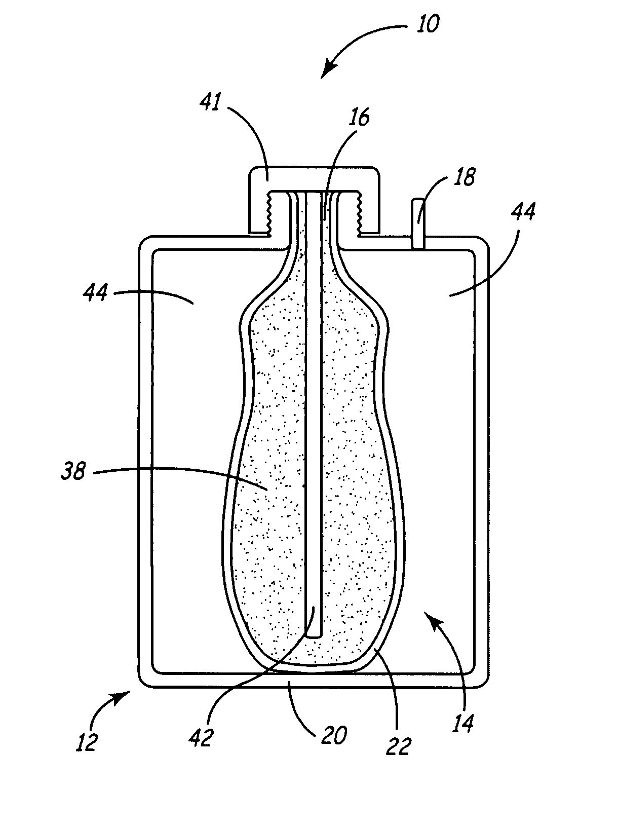
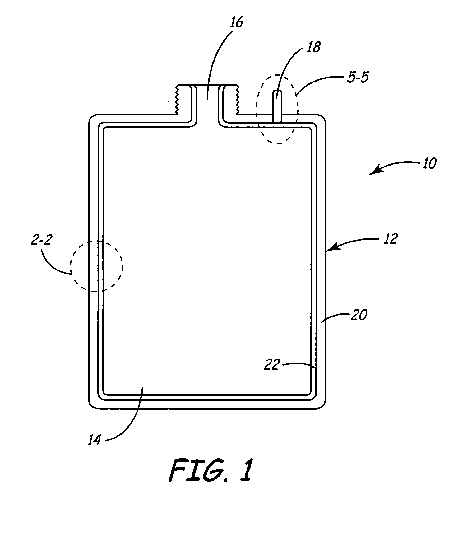
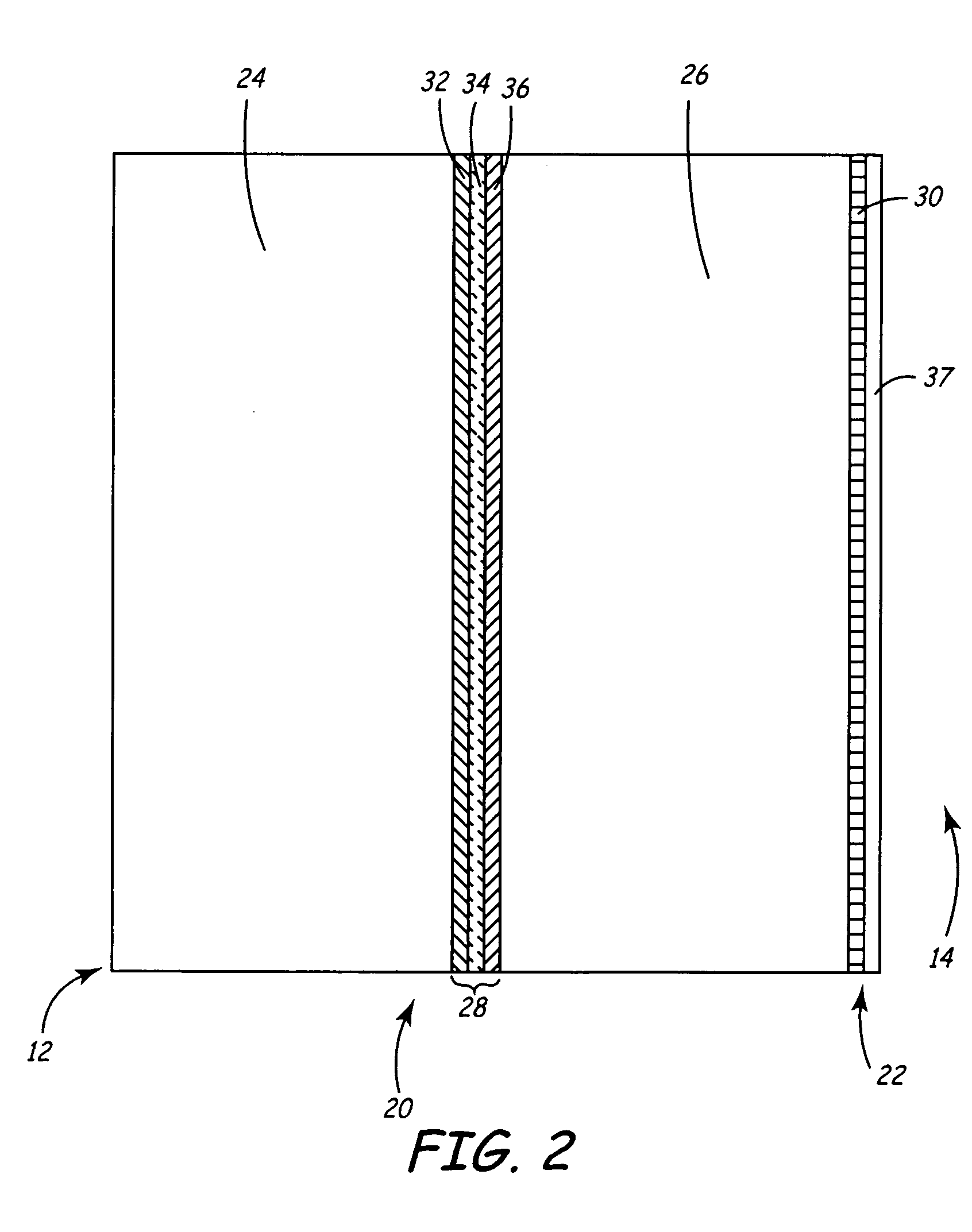
[0036] Liner portion 22 includes high-purity layer 37 (and tie layer 30 in the second embodiment). High-purity layer 37 is preferably a high-purity, high density polyethylene, and is the portion of bottle wall 12 that is exposed to cavity 14. High-purity layer 37 may alternatively consist of a high-purity, medium density polyethylene. Both polymers allow high-purity layer 37 to remain flexible enough to collapse within cavity 14. A high purity polymer is necessary for preventing contamination of ultrapure liquids retained in cavity 14.

[0037] As previously discussed, liner portion 22 is intrinsically formed with rigid portion 20 and tie layer 30 through the blow-molding process. This adds the benefit of preventing interstitial air from existing adjacent to liner portion 22. Typically, with collapsible-liner containers, interstitial air resides between the liner and the outer rigid wall. This presents a potential problem of the air permeating into the contained liquid over time, conta...

first embodiment

[0054] Additionally, in the first embodiment, gas inlet 18 is molded such that internal end 48 is positioned at a point between tie layer 30 and high-purity layer 37. This allows gas from the pressurized gas line (not shown) to flow between tie layer 30 and high-purity layer 37. Referring to FIG. 6, gas flows from the pressurized gas line (not shown) into external end 46 of gas inlet 18, designated by arrow A, and out through internal end 48, designated by arrow B. Because internal end 48 is positioned between tie layer 30 and high-purity layer 37, pressure increases between these layers, forcing high-purity layer 37 to peel away from tie layer 30, as designated by arrows C, D, and E, and collapse within cavity 14. The collapsing of high-purity layer 37 then pressure dispenses liquid 38 from cavity 14.

[0055] Accordingly, the first embodiment of the present invention combines the use of an adhesive contact having a weaker adhesive bond strength between rigid portion 20 and liner port...


PUM

PropertyMeasurementUnit
inner diameteraaaaaaaaaa
thicknessaaaaaaaaaa
thicknessaaaaaaaaaa

Abstract

A container for holding and dispensing liquid having a container wall comprising a rigid portion that dimensionally defines the container, a liner portion disposed within the container adjacent to the rigid portion, and an adhesive layer disposed between the rigid portion and the liner portion. The adhesive layer removably secures the liner portion to the rigid portion such that the liner portion is capable of being separated from the rigid portion and collapsed within the container, for dispensing the liquid.

Description

BACKGROUND OF THE INVENTION [0001] The present invention relates to a system for holding and dispensing liquids. In particular, the present invention relates to a container for holding and dispensing liquids having a collapsible liner intrinsically formed with the wall of the container. [0002] Numerous manufacturing processes require the use of ultrapure liquids such as acids, solvents, bases, photoresists, dopants, inorganic, organic and biological solutions, pharmaceuticals, and radioactive chemicals. Such industries require that the number and size of particles in the ultrapure liquids be controlled to ensure purity. In particular, because ultrapure liquids are used in many aspects of the microelectronic manufacturing process, semiconductor manufacturers have established strict particle concentration specifications for process chemicals and chemical-handling equipment. Such specifications are needed because, should the liquids used during the manufacturing process contain high le...

Claims


Application Information

Patent Timeline
Patent Type & Authority Applications(United States)
IPC IPC(8): B65D23/02B67D7/02
CPCB67D7/0261B65D23/02
Inventor ALBERG, MICHELE J.
Owner ADVANCED TECH MATERIALS INC
Why Eureka
Try Eureka