Method of manufacturing an optical lens

a manufacturing method and lens technology, applied in the field of customized optical lens manufacturing, can solve the problems of limited correction of blurred vision by fitting patients with lenses, affecting the optical performance of the eye, and affecting the patient's vision, etc., and achieve the effect of convenient and economical manufacturing methods

Inactive Publication Date: 2005-05-19
ENTERPRISE PARTNERS VI
View PDF6 Cites 68 Cited by
  • Summary
  • Abstract
  • Description
  • Claims
  • Application Information

AI Technical Summary

Benefits of technology

[0006] The system, method, and devices of the invention each have several aspects, no single one of which is solely responsible for its desirable attributes. Without limiting the scope of this invention as expressed by the claims which follow, its more prominent features will now be discussed briefly. After considering this discussion, and particularly after reading the section entitled “Detailed Description of Certain Embodiments” one will understand how the features of this invention provide advantages that include convenient and economical methods of manufacturing optical lens and lens blanks.
[0012] Yet another embodiment is method of making an optical lens. The method includes forming a substantially planar sheet of gel. The method further includes applying at least a portion of the substantially planar sheet of gel to the at least one surface of the mold to form a first layer of material having a selectively variable index of refraction. The method further includes forming a second layer of material within the mold. In one embodiment, the method further includes curing the first layer of material to define a pattern of refractive index. The pattern of refractive index may correct at least one high order aberration in an optical path through the optical lens.

Problems solved by technology

The human eye, namely the cornea and lens, can exhibit a variety of optical aberrations that diminish the optical performance of the eye, resulting in blurred vision.
The correction of blurred vision by fitting patients with lenses has typically been limited to the correction of low order aberrations only, such as defocus and astigmatism.
Traditionally, high order aberrations, e.g. those describable with Zernike polynomials of the third order or higher, could not be corrected using lenses.
In addition, due to lens manufacturing limitations and expenses, defocus and astigmatism are typically only corrected in discrete steps, with any correction being made to the nearest one quarter (0.25) diopter (D).
Unfortunately, the resolution of one quarter (0.25) diopter results in incomplete vision correction.

Method used


Image

  • Method of manufacturing an optical lens
  • Method of manufacturing an optical lens
  • Method of manufacturing an optical lens

Examples


Embodiment Construction

” one will understand how the features of this invention provide advantages that include convenient and economical methods of manufacturing optical lens and lens blanks.

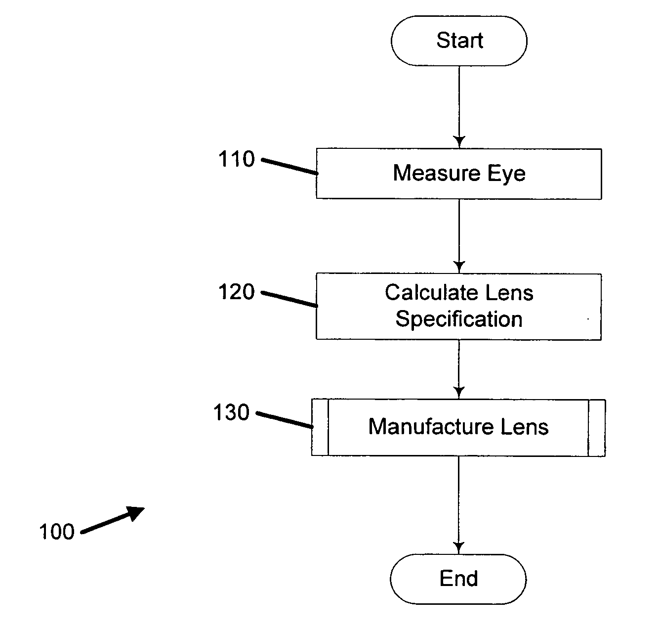
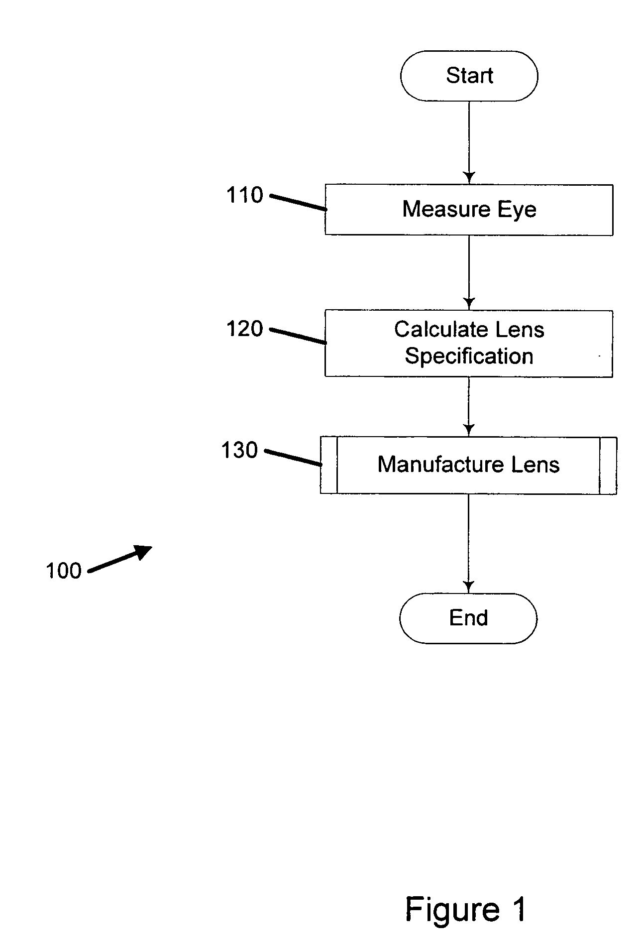
[0007] One embodiment is a method of customizing optical correction in an optical system. The method includes measuring optical aberration data of the optical system. The method further includes determining, based on the optical aberration data, a lens definition including a correction of at least one high order optical aberration. The method further includes fabricating a correcting lens based on the lens definition.

[0008] Another embodiment is a method of manufacturing a customized lens. The method includes measuring optical parameters of an optical system. The optical parameters may include measured optical aberrations. The method further includes forming a lens having at least one optical element. Forming the lens may include correcting a portion of the measured optical aberrations in the at least one optical el...


PUM

PropertyMeasurementUnit
thicknessaaaaaaaaaa
thickaaaaaaaaaa
temperatureaaaaaaaaaa

Abstract

A method of manufacturing an optical lens that is configured to correct high order aberrations. One embodiment is a method of customizing optical correction in an optical system. The method includes measuring optical aberration data of the optical system. The method further includes calculating a lens definition based on the optical aberration data. Calculating the lens definition may include calculating a correction of at least one high order optical aberration. The method further includes fabricating a correcting lens based on the lens definition.

Description

RELATED APPLICATIONS [0001] This application claims the benefit of, and incorporates by reference, U.S. Provisional Application No. 60 / 520,065 filed Nov. 14, 2003. This application also claims the benefit of, and incorporates by reference, U.S. Provisional Application No. 60 / 546,378, filed on Feb. 20, 2004.BACKGROUND OF THE INVENTION [0002] 1. Field of the Invention [0003] The present invention relates to systems and methods relating to manufacturing customized optical lenses for correcting aberrations of optical systems such as the human eye. [0004] 2. Description of the Related Art [0005] The human eye, namely the cornea and lens, can exhibit a variety of optical aberrations that diminish the optical performance of the eye, resulting in blurred vision. The correction of blurred vision by fitting patients with lenses has typically been limited to the correction of low order aberrations only, such as defocus and astigmatism. Traditionally, high order aberrations, e.g. those describa...

Claims


Application Information

Patent Timeline
Patent Type & Authority Applications(United States)
IPC IPC(8): B24B13/00B29C37/00B29C39/02B29C43/02B29D11/00G02C13/00
CPCB24B13/00B29C37/006B29C39/026B29C43/021G02C13/003B29D11/00442B29D11/00461B29D11/00528B29D11/00413B29D11/00355B29D11/0073G02C7/02G02C2202/22B29D11/00
Inventor JETHMALANI, JAGDISH M.WARDEN, LAURENCELAI, SHUI T.DREHER, ANDREAS W.
Owner ENTERPRISE PARTNERS VI
Why Eureka
Try Eureka