Method and system for deploying a mirror assembly from a recessed position

a mirror and recessed technology, applied in the field of mirror display systems, can solve the problems of not being able to detect, much less recognize, and the driver will not be able to detect that anything is there, so as to reduce the risk of a resulting accident, and eliminate the disadvantages

Inactive Publication Date: 2005-05-19
L 3 COMM CORP
View PDF53 Cites 8 Cited by
  • Summary
  • Abstract
  • Description
  • Claims
  • Application Information

AI Technical Summary

Benefits of technology

[0005] The present invention provides a method and system for deploying a mirror assembly from a recessed position that substantially eliminates or reduces at least some of the disadvantages and problems associated with previous methods and systems.

Problems solved by technology

On the other hand, if this same scenario occurs at night, particularly when the only illumination is from the headlights of the vehicle, the driver will not be able to detect that anything is there, much less recognize that it is a deer, because the deer will be beyond the range of the headlights.
Accordingly, the risk of a resulting accident is much higher at night than during the day.

Method used


Image

  • Method and system for deploying a mirror assembly from a recessed position
  • Method and system for deploying a mirror assembly from a recessed position
  • Method and system for deploying a mirror assembly from a recessed position

Examples


Embodiment Construction

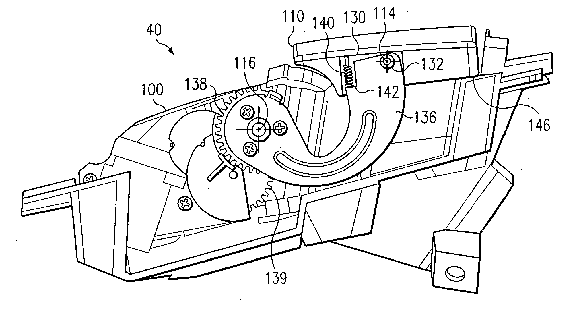
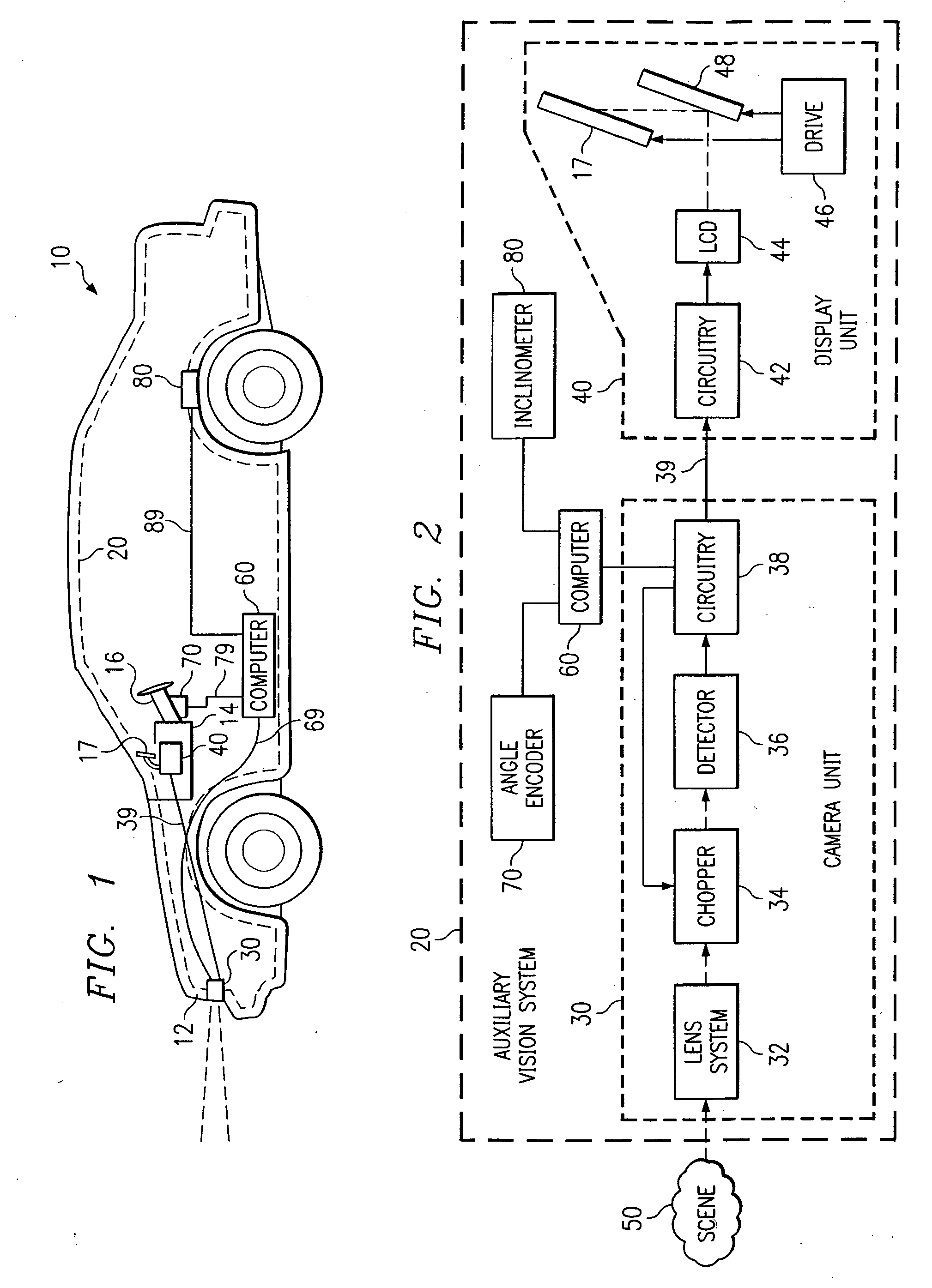
[0021]FIG. 1 is a diagrammatic view of a vehicle 10 incorporating one embodiment of an auxiliary vision system 20 in accordance with an embodiment of the present invention. The auxiliary vision system 20 includes a camera unit 30, which in the illustrated embodiment is mounted at the front of vehicle 10, in the middle of a front grill 12. The camera unit 30 is electrically coupled at 39 to a display unit 40, which is also a part of the auxiliary vision system 20. The display unit 40 is of a type that is commonly known as a head-up display (HUD). The display unit 40 is mounted within a recess of a dashboard 14 of the vehicle 10, and can project an image for reflection by a fold mirror of display unit 40 onto an imaging mirror 17 for display to the driver. Imaging mirror 17 is recessed within dashboard 14 when auxiliary vision system 20 is not in use. The imaging mirror 17 deploys out of dashboard 14 from a recessed position during operation of the system. As further described below, ...


PUM


Abstract

There is disclosed a method and apparatus for deploying a mirror assembly from a recessed position that includes rotating the mirror assembly in a first direction about a first axis, the mirror assembly coupled proximate the first axis to at least one lifting arm and rotating each lifting arm in a second direction about a second axis such that the mirror assembly moves to an operational position. The first direction may be opposite from the second direction.

Description

RELATED APPLICATIONS [0001] The present application is a divisional of U.S. Ser. No. 10 / 162,797 filed Jun. 4, 2002, entitled Method and System for Deploying a Mirror Assembly from a Recessed Position, now U.S. Pat. No. 6,808,274.TECHNICAL FIELD OF THE INVENTION [0002] This invention relates generally to mirror display systems and, more particularly, to a method and system for deploying a mirror assembly from a recessed position. BACKGROUND OF THE INVENTION [0003] During daylight hours, the driver of a vehicle is able to readily detect and recognize objects that would be difficult or impossible to detect or recognize at night. For example, assume that a deer wanders into the road approximately 500 meters ahead of the vehicle. If this scenario occurs in the middle of a sunny day, the driver will not only be able to detect the fact that something is present ahead, but will readily recognize that it is a deer. On the other hand, if this same scenario occurs at night, particularly when t...

Claims


Application Information

Patent Timeline
Patent Type & Authority Applications(United States)
IPC IPC(8): G02B27/00G02B27/01
CPCG02B2027/0138G02B27/0149
Inventor RAINES, AARON T.MENDEZ, TODD A.
Owner L 3 COMM CORP
Why Eureka
Try Eureka