Film bulk acoustic resonator (FBAR) devices with simplified packaging

a technology of acoustic resonators and films, applied in the direction of impedence networks, electrical devices, etc., can solve the problems of degrading the electrical properties of encapsulated fbar devices, stacks are no longer free to resonate, etc., and achieves sufficient acoustic isolation, simple and low-cost process

Active Publication Date: 2005-05-26
AVAGO TECH INT SALES PTE LTD
View PDF99 Cites 18 Cited by
  • Summary
  • Abstract
  • Description
  • Claims
  • Application Information

AI Technical Summary

Benefits of technology

[0015] The large ratio between the acoustic impedances of the metal of the metal Bragg layer and the plastic material of the plastic Bragg layer enables the acoustic Bragg reflector to provide sufficient acoustic isolation between the FBAR and the encapsulant for the frequency response of the FBAR device to exhibit minor, if any, spurious artifacts arising from undesirable acoustic coupling between the FBAR and the encapsulant.
[0016] The large ratio between the acoustic impedances of the metal of the metal Bragg layer and the plastic material of the plastic Bragg layer means that the FBAR device can typically be composed of between one and four Bragg layers in addition to the layers constituting the FBAR itself. This means that the fabrication process of the FBAR device in accordance with the invention is only slightly more complex than the fabrication process of a conventional FBAR device of the same type. The acoustic Bragg reflector allows a simpler and lower-cost process to be used to encapsulate the FBAR device.

Problems solved by technology

However, mechanical contact between the encapsulant and the top surface 68 of the FBAR stack remote from the substrate degrades the electrical properties of the encapsulated FBAR device because the FBAR stack is no longer free to resonate mechanically.

Method used


Image

  • Film bulk acoustic resonator (FBAR) devices with simplified packaging
  • Film bulk acoustic resonator (FBAR) devices with simplified packaging
  • Film bulk acoustic resonator (FBAR) devices with simplified packaging

Examples


exemplary embodiment 100

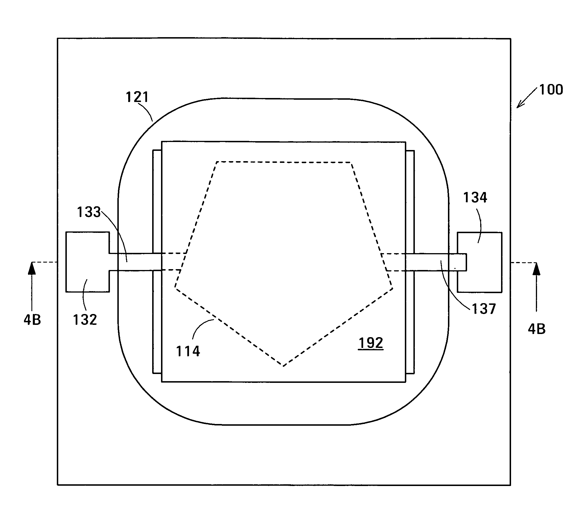
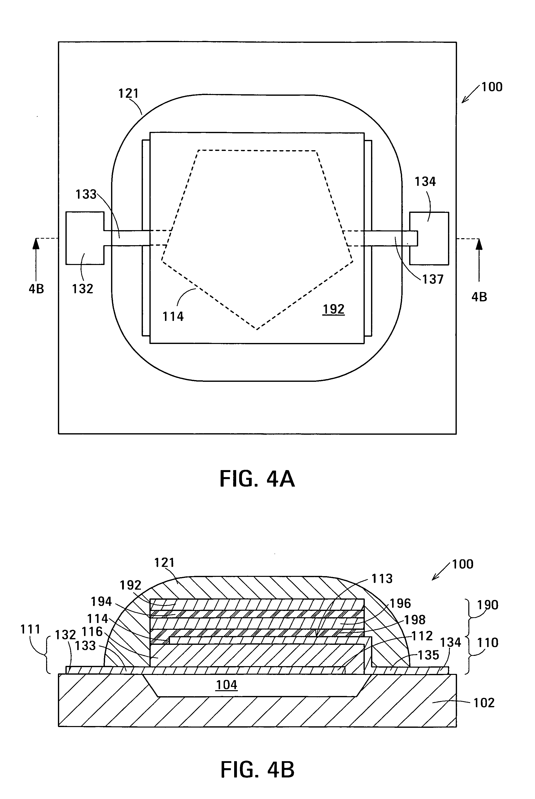
[0035]FIGS. 4A and 4B are respectively a plan view and a cross-sectional view of a first exemplary embodiment 100 of an encapsulated FBAR device in accordance with the invention. Encapsulated FBAR device 100 comprises an FBAR stack 111 comprising FBAR 110. FBAR 110 is an exemplary FBAR of an FBAR ladder filter, such as that shown in FIG. 1, or an exemplary FBAR of a duplexer. The remaining FBARs of such ladder filter or duplexer also constitute part of FBAR stack 111. However, the remaining FBARs are omitted from FIGS. 4A and 4B to simplify the drawing.

[0036] Referring to FIG. 4B, encapsulated FBAR device 100 is composed of a substrate 102, an FBAR stack 111 over the substrate, an element that isolates the FBAR stack from the substrate, encapsulant 121 covering FBAR stack 111, and an acoustic Bragg reflector 190 between the top surface 113 of FBAR stack 111 and encapsulant 121. Acoustic Bragg reflector 190 comprises a first metal Bragg layer 192 juxtaposed with a first plastic Bragg...

exemplary embodiment 200

[0067]FIG. 5 is a cross-sectional view of a second exemplary embodiment 200 of an encapsulated FBAR device in accordance with the invention. Encapsulated FBAR device 200 is similar in plan view to encapsulated FBAR device 100 shown in FIG. 4A. Encapsulated FBAR device 200 comprises FBAR stack 111 comprising FBAR 110. FBAR 110 is an exemplary FBAR of an FBAR ladder filter, such as that shown in FIG. 1, or an exemplary FBAR of a duplexer. The remaining FBARs of such ladder filter or duplexer also constitute part of FBAR stack 111. However, the remaining FBARs are omitted from FIG. 5 to simplify the drawing. Elements of encapsulated FBAR device 200 that correspond to elements of encapsulated FBAR device 100 described above with reference to FIGS. 4A and 4B are indicated using the same reference numerals and will not be described in detail again here.

[0068] Encapsulated FBAR device 200 is composed of substrate 102, FBAR stack 111 over the substrate, an element that isolates the FBAR sta...

exemplary embodiment 300

[0075]FIGS. 6A and 6B are respectively a plan view and a cross-sectional view of a third exemplary embodiment 300 of an encapsulated FBAR device in accordance with the invention. FBAR device 300 is a band-pass filter in which the FBAR stack is composed of two FBARs and an acoustic decoupler between the FBARs. The FBARs and the acoustic decoupler constitute a single decoupled stacked bulk acoustic resonator (DSBAR). The example of FBAR device 300 shown in FIGS. 6A and 6B and described below has an acoustic Bragg reflector similar in structure to acoustic Bragg reflector 190 described above with reference to FIGS. 4A and 4B located between the top surface of the FBAR stack and the encapsulant to isolate the FBAR stack acoustically from the encapsulant. The acoustic Bragg reflector may alternatively be structured as described above with reference to FIGS. 4C and 4D. In the example of FBAR device 300 shown in FIGS. 6A and 6B and described below, the FBAR stack is suspended over a cavity...


PUM


Abstract

The encapsulated film bulk acoustic resonator (FBAR) device comprises a substrate, an FBAR stack over the substrate, an element for acoustically isolating the FBAR stack from the substrate, encapsulant covering the FBAR stack, and an acoustic Bragg reflector between the top surface of the FBAR stack and the encapsulant. The FBAR stack comprises an FBAR and has a top surface remote from the substrate. The FBAR comprises opposed planar electrodes and a piezoelectric element between the electrodes. The acoustic Bragg reflector comprises a metal Bragg layer and a plastic Bragg layer juxtaposed with the metal Bragg layer. The large ratio between the acoustic impedances of the metal of the metal Bragg layer and the plastic material of the plastic Bragg layer enables the acoustic Bragg reflector to provide sufficient acoustic isolation between the FBAR and the encapsulant for the frequency response of the FBAR device to exhibit minor, if any, spurious artifacts arising from undesirable acoustic coupling between the FBAR and the encapsulant.

Description

RELATED APPLICATION [0001] This application is a Continuation-in-Part of the following U.S. patent applications: Ser. No. 10 / 699,289 of John D. Larson III entitled Stacked Bulk Acoustic Resonator Band-Pass Filter with Controllable Pass Bandwidth, Ser. No. 10 / 699,481 of John D. Larson III and Richard Ruby entitled Thin-Film Acoustically-Coupled Transformer, Ser. No. ______ of John D. Larson III, Richard Ruby and Stephen Ellis entitled Decoupled Stacked Bulk Acoustic Resonator Band-Pass Filter with Controllable Pass Bandwidth (Agilent Docket No. 10041305-1), and Ser. No. ______ of John D. Larson III, Richard Ruby and Stephen Ellis entitled Film Acoustically-Coupled Transformer (Agilent Docket No. 10041306-1). The application is also related to U.S. patent application Ser. No. ______ of John D. Larson III, Stephen Ellis, Paul A. Bradley and Yury Oshmyansky entitled Cavity-less Film Bulk Acoustic Resonator (FBAR) Devices, filed on the same day as this application. The above applications...

Claims


Application Information

Patent Timeline
Patent Type & Authority Applications(United States)
IPC IPC(8): H01L41/22H01L41/23H03H9/02H03H9/13H03H9/58H03H9/60
CPCH03H9/02102H03H9/132H03H9/175H03H9/605H03H9/587H03H9/589H03H9/584H03H9/13H03H9/60H03H9/171H03H9/58H03H9/0095
Inventor LARSON, JOHN D. IIIELLIS, STEPHENOSHMYANSKY, YURY
Owner AVAGO TECH INT SALES PTE LTD
Why Eureka
Try Eureka