Lenticular display backlit by an electro-luminescent light source

Inactive Publication Date: 2005-05-26
LIGHTSPORT PRODS
View PDF12 Cites 13 Cited by
  • Summary
  • Abstract
  • Description
  • Claims
  • Application Information

AI Technical Summary

Benefits of technology

[0006] In view of the aforesaid drawback of the conventional systems, it is an object of the present invention to proved a more effective luminescent system for use on a garment allowing a greater degree of brightness and greater control over the details of the display.
[0007] In one embodiment the invention comprises a garment having attached to a surface thereof a display module that comprises a substantially flat PVC envelope having a transparent front surface. Inside the envelope is an electro-luminescent lamp layer and a translucent lenticular lens layer that has the effect of diffusing the light from the electro-luminescent lamp layer.
[0008] To energize the electro-luminescent lamp layer an electrical signal is brought from a battery power source and an

Problems solved by technology

However the combination in a garment having a lenticular translucent design backlit by an electro-luminescent layer is not previously

Method used


Image

  • Lenticular display backlit by an electro-luminescent light source
  • Lenticular display backlit by an electro-luminescent light source
  • Lenticular display backlit by an electro-luminescent light source

Examples


Embodiment Construction

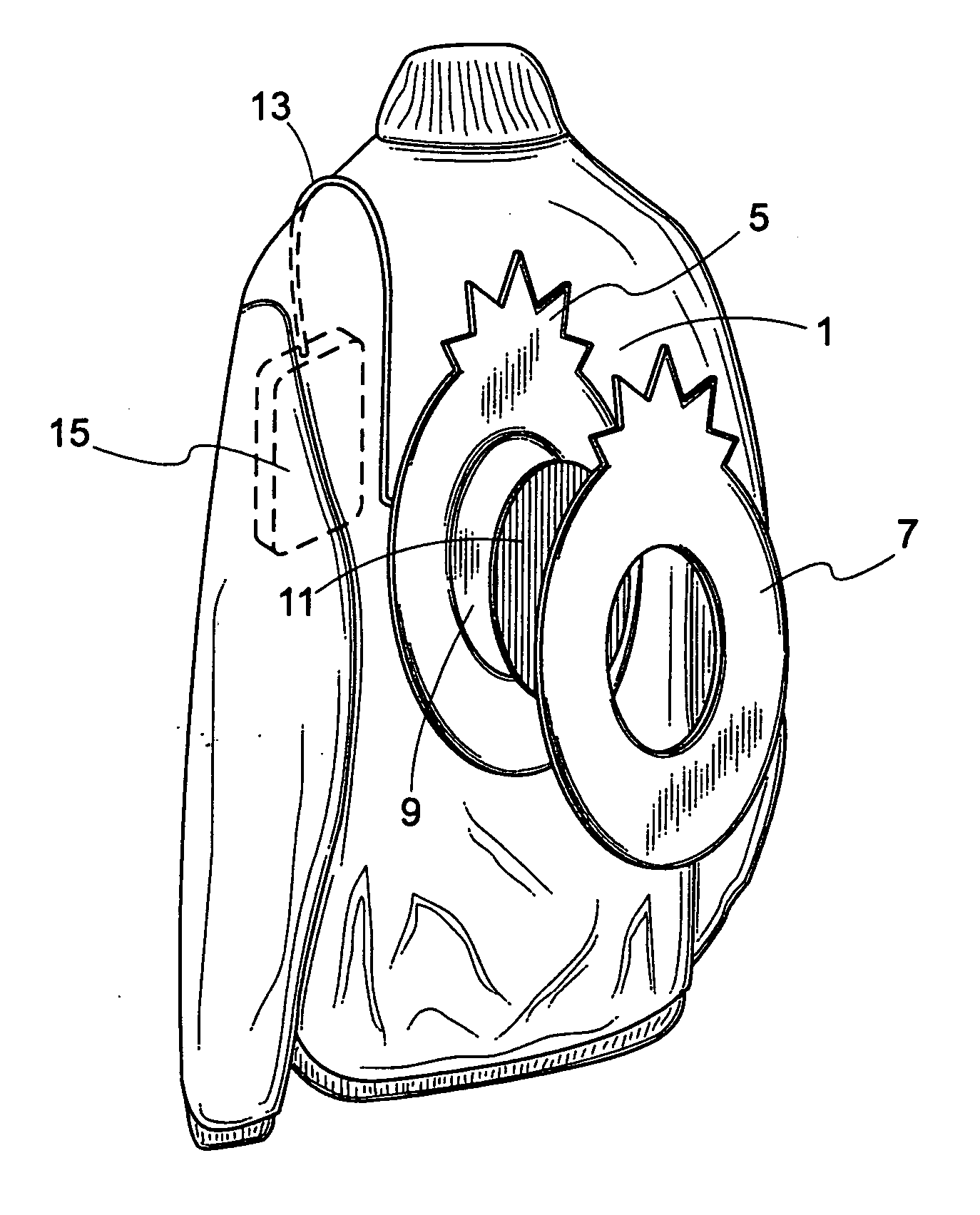
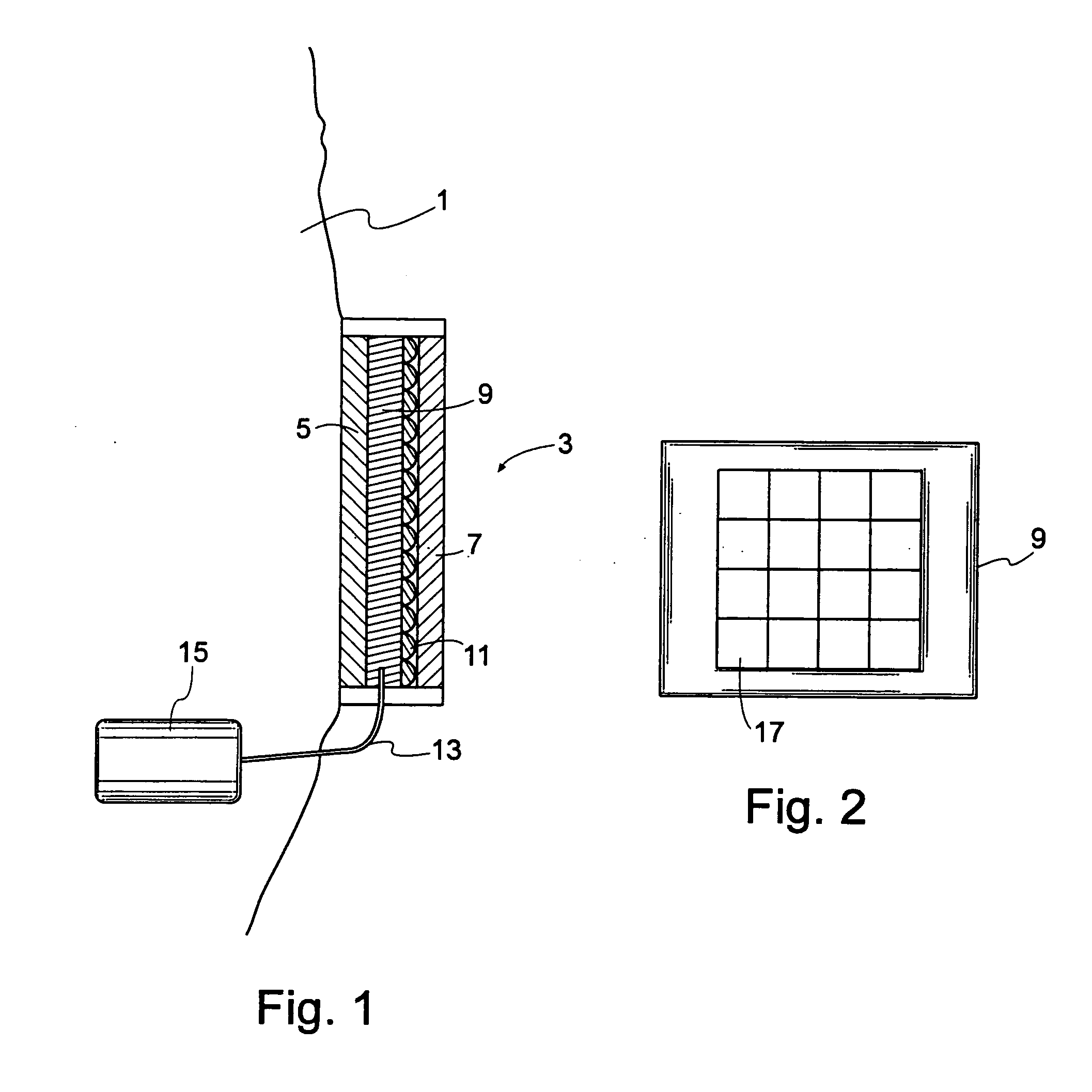
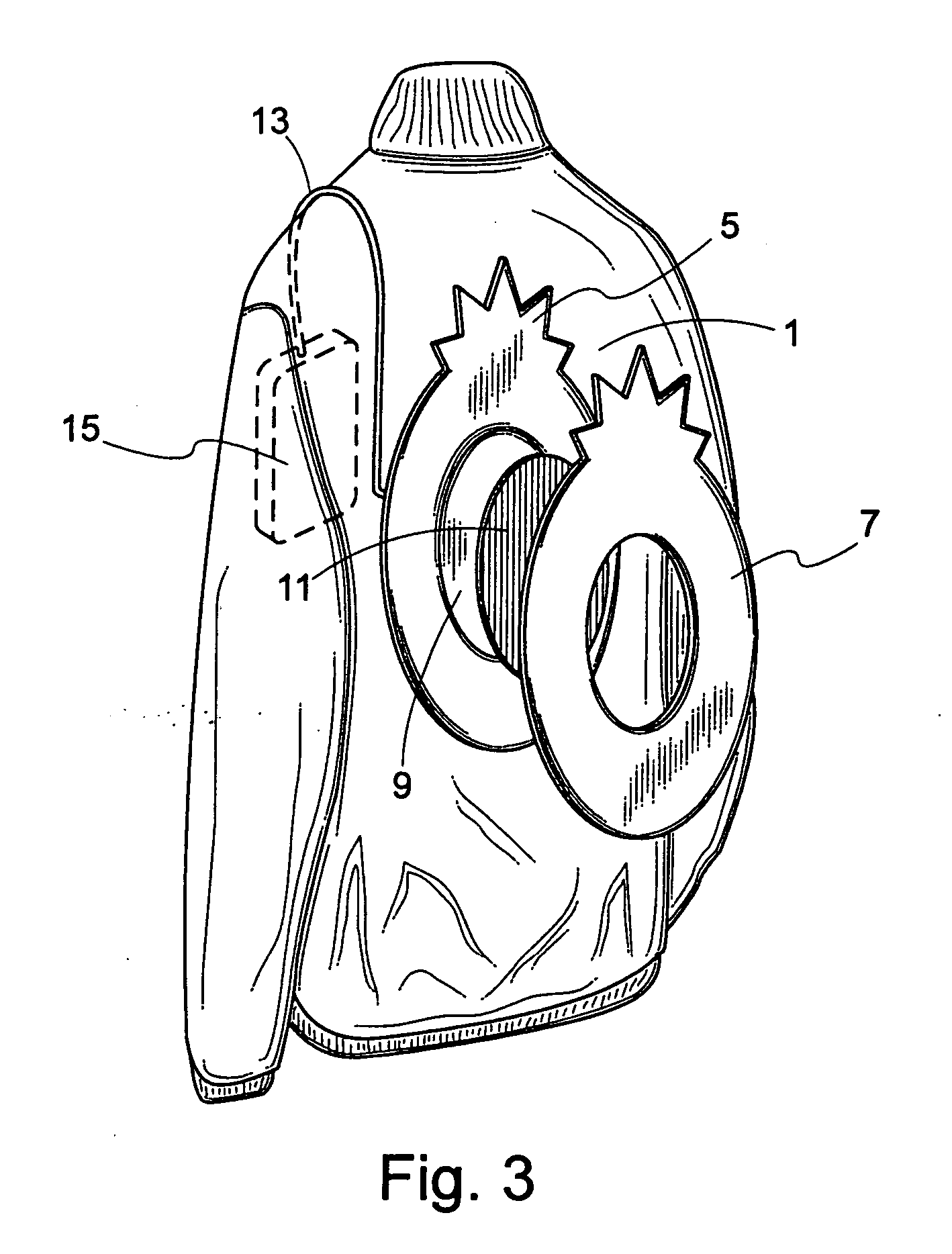
[0013] As shown in FIG. 1, a garment 1 has attached to a surface thereof a display module 3. The module may be attached either permanently by being sewn or stapled to the garment or by use of a removable attachment mechanism such as velcro, snaps, zippers or the like. The module 3 comprises an envelope having a transparent surface such as a substantially flat PVC envelope having a back surface 5 for attachment to the garment 1 and a transparent front surface 7. The transparency of the front surface 7 need not be total, but need only be sufficiently transparent to allow light from inside the envelope to escape through the front surface. Inside the envelope is an electro-luminescent lamp layer 9 in contact with the back surface of the envelope. In contact with this layer is a lenticular lens layer 11, which is in contact with the front surface 7 of the PVC envelope. The lenticular lens layer 11 is preferably translucent and has the effect of diffusing the light from the electro-lumine...


PUM


Abstract

The present invention provides an article of clothing with a backlit translucent lenticular lens display that emits light that allows animation and special effects by design which can distinguish the user by the performance of an article of clothing. A garment has attached to a surface a display module having a substantially flat PVC envelope enclosing an electro-luminescent lamp layer and a translucent lenticular lens layer. The electro-luminescent lamp layer is energized by an electrical signal from an control electronic circuit. The electro-luminescent layer may be divided into segments where each segment functions as an independent electro-luminescent layer receiving a potential having a pattern of illumination that is determined by the control electronic circuit. The invention can be used in safety apparel where the resulting pattern is a bright surface having the shape of a caution warning.

Description

CROSS-RELATED APPLICATIONS [0001] The present application claims priority from Provisional Application Ser. No. 60 / 497,001, filed Aug. 20, 2003, entitled “Lentricular Display Backlit by an Electro-Luminescent Light Source”, by the same inventors.BACKGROUND OF THE INVENTION [0002] 1. Field of the Invention [0003] This invention is related to garments having dynamic optical displays on their surface. In particular it is related to such displays employing an electro-luminescent light source. [0004] 2. Description of the Prior Art [0005] Garments are known that have designs on acetate layers illuminated by an electro-luminescent lamp. Garments and accessories with lenticular layers are also known. The combination of a lenticular luminescent screen having a base plate of a transparent material containing a substance capable of emitting luminescent light in response to stimulating light is known in U.S. Pat. No. 5,021,931. However the combination in a garment having a lenticular transluce...

Claims


Application Information

Patent Timeline
IPC IPC(8): A41DA41D13/01F21V9/16
CPCA41D13/01G09F21/02G09F19/12
Inventor ONO, BRYAN K.
Owner LIGHTSPORT PRODS
Why Eureka
Try Eureka