Cleaning Tool for Floor Surfaces Having an Illumination Element for a Working Area

Inactive Publication Date: 2005-06-02
DUPRO AG
View PDF8 Cites 36 Cited by
  • Summary
  • Abstract
  • Description
  • Claims
  • Application Information

AI Technical Summary

Benefits of technology

[0010] In a preferred embodiment, the bearing plate is comprised of an elastic material, preferably of a soft-elastic material, particularly rubber, so that the manufacturing and mounting tolerances can be compensated easily without this having an effect on the support action of the brush roller.
[0011] In order to ensure a safe securing action of the support plate in the bearing receptacle, it can be advantageous to match the bottom of the bearing receptacle to the circumferential geometry of the support plate. A simple ele

Problems solved by technology

The rod-shaped incandescent lamp is exposed to high mechanical loads because it is provided on the end face of the housing that is exposed to mechanical loads by imp

Method used


Image

  • Cleaning Tool for Floor Surfaces Having an Illumination Element for a Working Area
  • Cleaning Tool for Floor Surfaces Having an Illumination Element for a Working Area
  • Cleaning Tool for Floor Surfaces Having an Illumination Element for a Working Area

Examples


Embodiment Construction

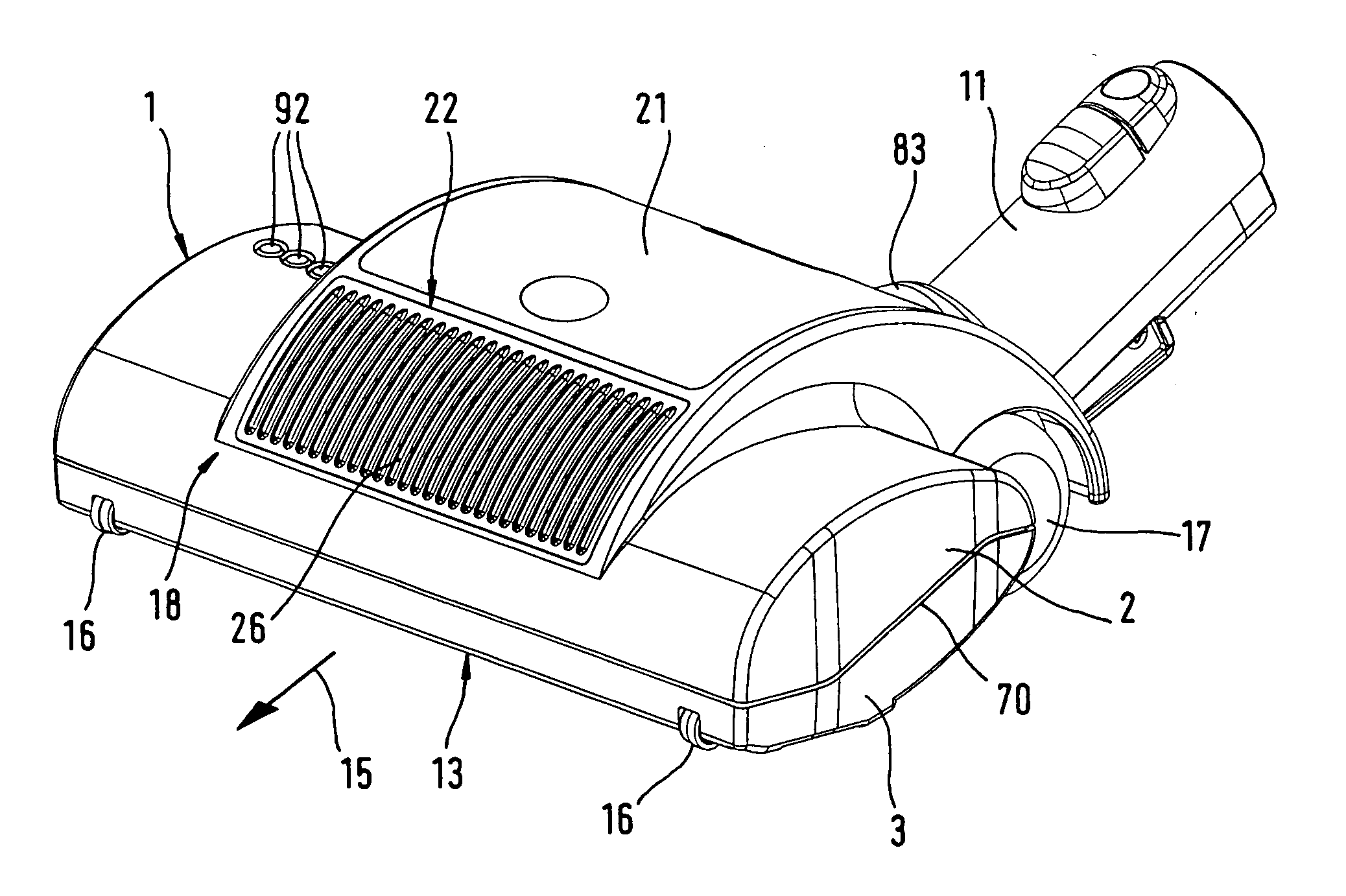
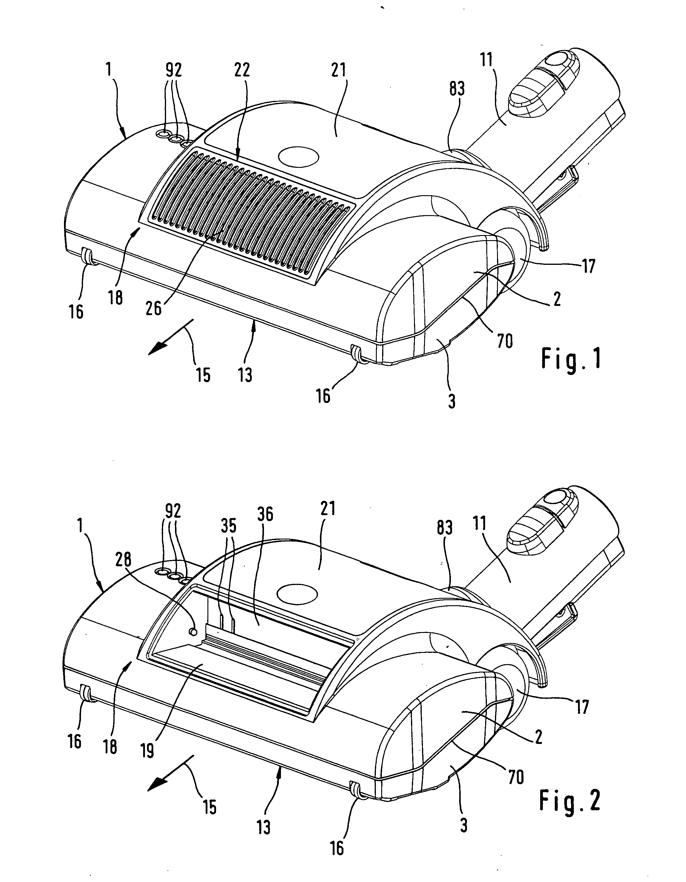
[0026] The cleaning tool for floor surfaces, upholstery surfaces or the like, as illustrated in the drawings, is configured as a vacuum cleaning tool for a vacuum cleaning device such as a vacuum cleaner. It is comprised of, as shown in FIGS. 1 and 2, of a two-part housing 1 with a top cover 2 and a bottom part 3. FIGS. 6 through 8 show that a working chamber 4 is provided in the housing 1 and a brush roller 5 is arranged in the working chamber 4 and driven so as to rotate about an axis of rotation 6. The drive action is realized by a belt drive 7 that, in the illustrated embodiment, is driven by a drive motor 8. The drive motor 8 is part of a drive unit 9 that can be inserted as a module into the motor chamber 10 of the housing 1. The motor chamber 10 is separated from the working chamber 4 wherein the working chamber 4 in the illustrated embodiment is connected by a vacuum connector 11 to a vacuum cleaning device. The connection between the working chamber 4 and the vacuum connect...


PUM


Abstract

A vacuum cleaning tool for a vacuum cleaning device has a housing with a working chamber that has a bottom plate provided with a suction slot extending transversely to a working direction of the vacuum cleaning tool. The housing has a housing front wall facing in the working direction. The housing front wall has a receptacle, and an illumination element is arranged in the receptacle for illuminating a working surface of the vacuum cleaning tool. A light-permeable cover closes off the receptacle and covers the illumination element. The illumination element is a cold light lamp emitting cold light.

Description

BACKGROUND OF THE INVENTION [0001] The invention relates to a cleaning tool for floor surfaces, upholstery surfaces or the like, in particular, a vacuum cleaning tool for vacuum cleaning devices such as a vacuum cleaner. The cleaning tool is comprised of a housing having a working chamber whose bottom plate comprises a suction slot that extends transversely to the working direction of the cleaning tool and is designed for taking up dirt. The cleaning tool further comprises a forwardly facing housing end wall provided with a receptacle for an illumination element for illuminating the surface to be cleaned, wherein the illumination element is arranged behind a light-permeable cover. [0002] Such a vacuum cleaning tool is disclosed in U.S. Pat. No. 5,896,618. This patent proposes to arrange a rod-shaped incandescent lamp at the housing end face of the cleaning tool for providing a sufficient illumination of the working area. The rod-shaped incandescent lamp is exposed to high mechanical...

Claims


Application Information

Patent Timeline
IPC IPC(8): A47L5/00A47L9/02A47L9/04A47L9/30
CPCA47L9/02A47L9/30A47L9/2857A47L9/2836
Inventor WORWAG, PETER
Owner DUPRO AG
Why Eureka
Try Eureka