Zero backlash steering gear

Inactive Publication Date: 2004-02-12
ROBERT BOSCH GMBH
View PDF6 Cites 29 Cited by
  • Summary
  • Abstract
  • Description
  • Claims
  • Application Information

AI Technical Summary

Benefits of technology

0012] By the pivoting motion of the shaft in the radial direction, a play-free engagement between the pinion and the gear wheel can be established, which can be compensated for readily even if wear occurs to the gear wheel bearings or to the gear wheels. No additional stresses on the gear components occur. It is also possible simply and precisely to define the contact pressure between the pinion and the gear wheel, so that the gear friction is no greater than absolutely necessary, and thus the restoration of the vehicle steering system to the center position is not significantly hindered. Moreover, the pinion cannot be displaced in the axial direction, and this enhances the steering precision.
0013] The object stated above is also attained by a gear for a vehicle steering system, having a pinion disposed on a shaft in a manner fixed against relative rotation, having a rack that meshes with the pinion, the pinion and the rack being prestressed in the radial direction, and in which the shaft is supported pivotably in the radial direction. In this rack-and-pinion gear according to the invention, the aforementioned advantages come into play in the same way.
0014] In a variant of the invention it is provided that the shaft is supported in a housing by means of a fixed bearing and at least one movable bearing; and that the movable bearing or movable bearings are displaceable in the radial direction in the housing, and/or that the housing has an

Problems solved by technology

In these gears, play is unwanted, since it makes the steering feel worse, makes the steering interventions less precise, and moreover it makes itself felt unpleasantly in the form of "cracking noises" when there is a change in the direction of rotation.
A disadvantage of this steering gear is that the precision of the steering motion suffers, and a compensation in length is necessary between the pinion shaft and the electric motor that drives the pinion shaft.
A disadvantage of this version is that wear of the gear

Method used


Image

  • Zero backlash steering gear
  • Zero backlash steering gear
  • Zero backlash steering gear

Examples


Embodiment Construction

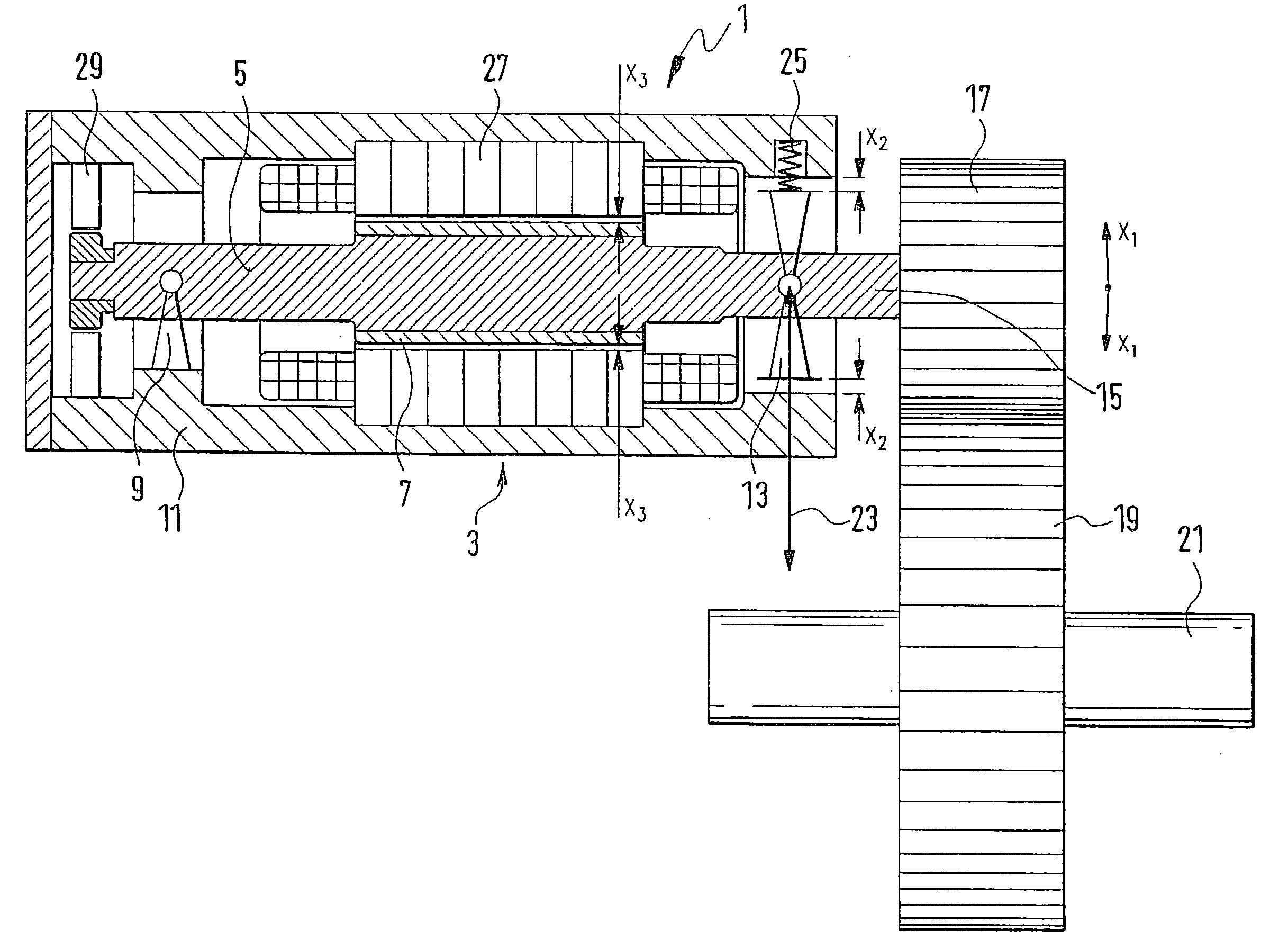
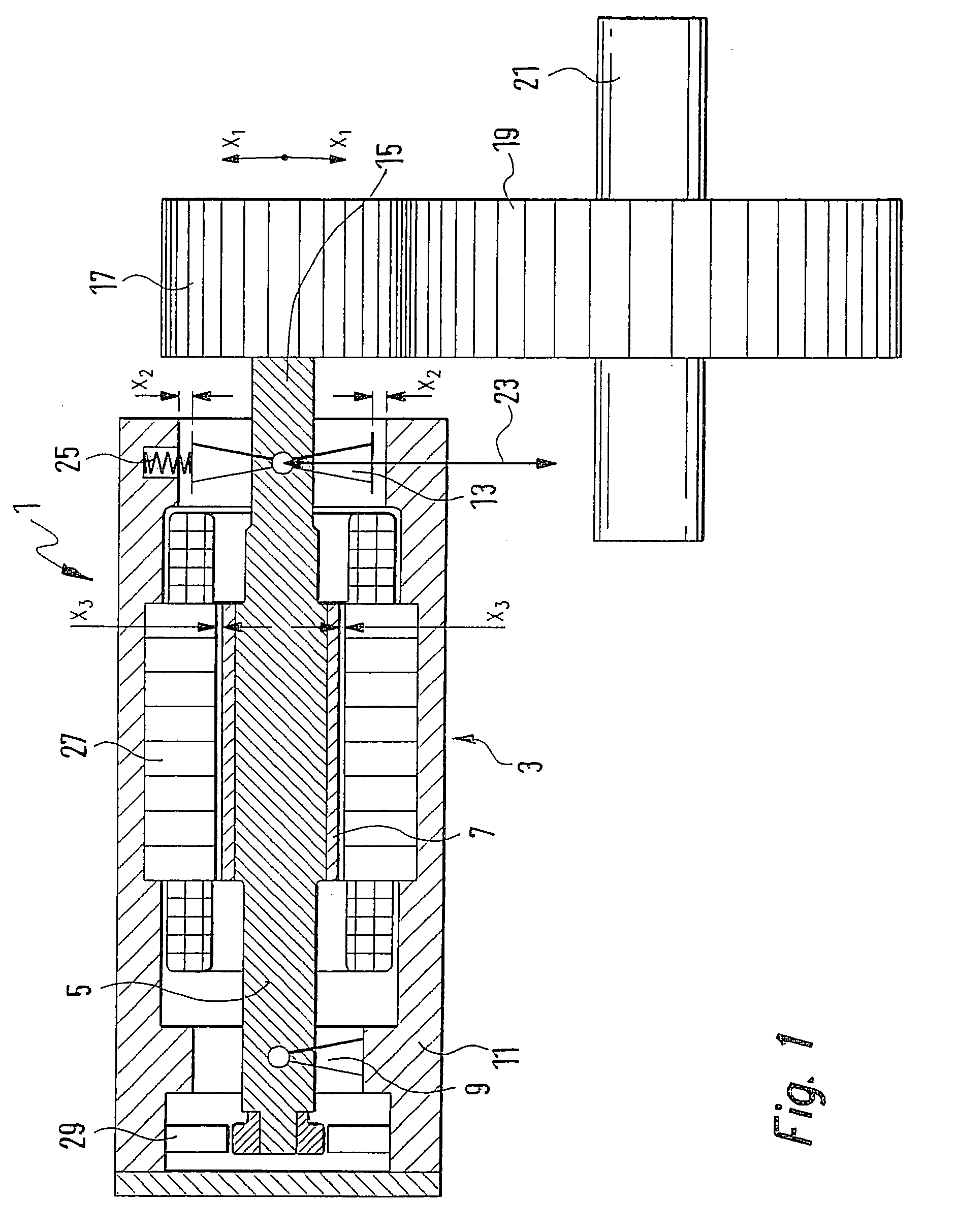
[0027] In FIG. 1, a first exemplary embodiment of a gear 1 of the invention with spur toothing. The gear 1 comprises an electric motor 3, with a shaft 5 that carries a rotor 7. The shaft 5 is supported by one end with a fixed bearing 9, shown only schematically, in a housing 11 of the electric motor 3. On the opposite end of the electric motor 3, there is a movable bearing 13. A pinion 17 is secured in a manner fixed against relative rotation to a journal 15 of the shaft 5. The pinion 17 is thus cantilevered on the shaft 5 and meshes with a gear wheel 19, which is secured to a power takeoff shaft 21. The bearing of the power takeoff shaft 21 is not shown in FIG. 1.

[0028] To prevent play in the toothing between the pinion 17 and the gear wheel 19, the shaft 5 can be pivoted about the fixed bearing 9 in the direction of the arrows X1. The pivoting motion of the shaft 5 is made possible by the fact that the movable bearing 13 is secured displaceably in the housing 11 in the radial dire...


PUM


Abstract

A gear for vehicle steering systems is proposed, in which, by pivoting a shaft (5) of a pinion (17) in the radial direction (23) by means of a spring element (25), play-free transmission of the rotary motion from the shaft (5) to a power takeoff shaft (21) is assured.

Description

PRIOR ART[0001] The invention relates to a gear for a vehicle steering system, having a pinion disposed on a shaft in a manner fixed against relative rotation, having a gear wheel that meshes with the pinion, the pinion and the gear wheel being prestressed in the radial direction.[0002] Conventional vehicle steering systems, vehicle steering systems with an overriding gear, and steer-by-wire steering systems require one or more steering gears with which the rotary motion of the steering wheel is converted into a rotary motion of the steered wheels.[0003] In conventional electric power steering systems, a torque brought to bear by an electric motor must be input into the steering system as well. In a steer-by-wire steering system, there is no mechanical or hydraulic connection between the steering wheel and the steered vehicle wheels. A steering actuator regulates the position of the steered vehicle wheels as a function of the driver's steering demand and such other variables as the ...

Claims


Application Information

Patent Timeline
IPC IPC(8): B62D3/02B62D5/04F16H1/06F16H1/16F16H1/28F16H57/022F16H57/12
CPCB62D5/0409F16H1/26Y10T74/1967F16H57/022F16H2057/127F16H55/24F16C2380/27F16C19/546F16C2229/00
Inventor BOCK, MICHAELNAGEL, WILLIKNECHT, ROLF
Owner ROBERT BOSCH GMBH
Why Eureka
Try Eureka